BUNN ® FMD-1 (prior to S/N FMD0013000) SH PU RE LE D OL dH an AS EB ON TT BU UT TO N TIL UN E WH N P IS CU CU 2/3 P IS N HE ,T LL FU 2/3 FU E AS LE RE LL E AC RE PL HE P CU OPERATING & SERVICE MANUAL BUNN-O-MATIC CORPORATION POST OFFICE BOX 3227 SPRINGFIELD, ILLINOIS 62708-3227 PHONE: (217) 529-6601 FAX: (217) 529-6644 28364.
INTRODUCTION This equipment dispenses hot beverages on demand from powered product. It is for indoor use only on a sturdy counter or shelf. WARRANTY Bunn-O-Matic Corp. (“Bunn”) warrants the equipment manufactured by it to be commercially free from defects in material and workmanship existing at the time of manufacture and appearing within one year from the date of installation. In addition: 1.
USER NOTICES (Cont.) 00656.0000 00831.0000 28368.0000 PUSH and HOLD BUTTON UNTIL CUP IS 2/3 FULL, THEN RELEASE 28301.
INITIAL SET-UP 1. 2. 3. 4. Locate the drip tray assembly beneath the dispenser nested in the packing material. Remove the drip tray and the drip tray cover and set them aside. Remove the water strainer assembly from the drip tray and set it aside. Remove the four legs from the drip tray, apply non-skid pads to the bottom of the legs and securely install the legs in the dispenser base.
PLUMBING HOOK-UP 1. 2. 3. Securely attach the short piece of tubing on the water strainer assembly to the inlet fitting on the bottom of the dispenser. Flush the water line and securely attach it to the flare fitting on the water strainer assembly. Turn-on the water supply. INITIAL FILL & HEAT CAUTION - The dispenser must be disconnected from the power source throughout the initial set-up, except when specified in the instructions. 1. 2.
DRAINING THE HOT WATER TANK CAUTION - The dispenser must be disconnected from the power source throughout these steps. 1. Disconnect the dispenser from the power source. 2. Open front door and place tank heater switch in the “OFF” (upper) position. 3. Shut-off and disconnect the incoming water supply. 4. Remove the top panel. 5. Gently remove one of the grommets from the tank lid. 6. Insert a tube to the bottom of the tank and syphon ALL of the water out. (Bunn-O-Matic has a syphon assembly #12440.
TROUBLESHOOTING A troubleshooting guide is provided to suggest probable causes and remedies for the most likely problems encountered. If the problem remains after exhausting the troubleshooting steps, contact the Bunn-O-Matic Technical Service Department. • • • • • • • Inspection, testing, and repair of electrical equipment should be performed only by qualified service personnel. All electronic components have 120 volt ac and low voltage dc potential on their terminals.
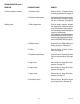
TROUBLESHOOTING (cont.) PROBLEM PROBABLE CAUSE REMEDY Product will not dispense (cont.) 5. Solenoid valve (inlet) Refer to Service - Solenoid Valve (Inlet) for testing procedures. See page 27 6. Level control board and probe Refer to Service - Level Control Board and Probe for testing procedures. See page 22 7. Overflow protection switch Refer to Service - Overflow protection switch for testing procedures. See page 24 8. Auger drive Refer to Service - Auger Drive. See page 12 9.
TROUBLESHOOTING (cont.) PROBLEM PROBABLE CAUSE REMEDY Water is not hot (Cont.) 4. Tank heater switch Refer to Service - Tank Heater Switch for testing procedures. See page 29 Spitting or excessive steaming 1. Lime build-up Inspect tank assembly for excessive CAUTION - Tank and tank compo- lime deposits. Delime as required. nents should be delimed regularly depending on local water conditions.
TROUBLESHOOTING (cont.) PROBLEM PROBABLE CAUSE REMEDY Product overflows container 1. Dispense switch Refer to Service - Dispense Switch for testing procedures. See page 16 2. Dispense solenoid valve Remove the solenoid valve and clear any obstructions. Rebuild or replace the valve if necessary. See page 26 1. Water temperature Place an empty container beneath the dispense tip. Initiate a dispense cycle and check the water temperature immediately below the dispense tip with a thermometer.
TROUBLESHOOTING (CONT.) PROBLEM PROBABLE CAUSE Dispenser is making unusual noises 1. Plumbing Lines 2. Water Supply REMEDY Plumbing lines should not be resting on the counter top. (A) The dispenser must be connected to a cold water line (B) Water pressure to the dispenser must not exceed 90 psi (620 kPa). Install a regulator if necessary to lower the working pressure to approximately 50 psi (345 kPa). Excess dust Display not lit 3. Tank Heater Remove and clean lime off the tank heater.
AUGER DRIVE COMPONENTS SERVICE This section provides procedures for testing and replacing various major components used in this dispenser should service become necessary. Refer to Troubleshooting for assistance in determining the cause of any problem. WARNING - Inspection, testing, and repair of electrical equipment should be performed only by qualified service personnel.
SERVICE AUGER DRIVE COMPONENTS (CONT.) 1 5. 2 With the wires removed from the motor . Check for continuity across the two terminals on the bottom of the auger motor. If continuity is present as described, refer to Fig.3 and reconnect the wires to the terminals on the bottom of the auger motor, the auger motor is operating properly. If continuity is not present as described, replace the auger motor. 3 4 5 14 15 16 6 7 8 9 10 11 Removal, Cleaning and Replacement Hopper & Auger 1.
BALLAST SERVICE (cont.) AUGER DRIVE COMPONENTS (cont.) Auger Drive Motor (Refer to Fig. 2) 1. Remove hopper assy (18), and set aside for reassembly. 2. Remove the four #8-32 screws securing the hopper support plate (13), remove plate and set aside for reassembly. 3.
SERVICE (cont.) 5. Disconnect the dispenser from the power source. BALLAST (cont.) If voltage is present as described the control thermostat is operating properly. Reinstall bulb into the tank. If voltage is not present as described, replace the thermostat. BLK to Main Wiring Harness Removal and Replacement. 1. Disconnect the wires from the thermostat. 2. Remove the thermostat capillary bulb by firmly pulling-up on the capillary at the tank lid. This will disengage the grommet from the tank lid. 3.
the switch in the“ON” pressed position. Continuity must not be present when the switch is in the “OFF” released position. SERVICE (cont.) DISPENSE SWITCH If continuity is present as described, reconnect the connector to the door interconnect wiring harness, the switch is operating properly. If continuity is not present as described, replace the switch. Removal and Replacement 1. Open the dispenser door. 2. Remove the five #6-32 screws securing the bottom door cover and remove cover. 3.
SERVICE (cont.) Removal and Replacement: 1. Disconnect the vacuum hose from the fan. 2. Remove the two #8-32 locking screws securing the fan to the dispenser housing base plate. 3. Disconnect the wires from the fan terminals and discard the fan 4. Refer to Fig. 11 and connect the wires to the new fan. 5. Install new fan through the rear access hole and secure to the dispenser housing base plate using two #8-32 locking screws. 6. Reconnect the vacuum hose to the fan. FAN BLK from Control Harness FIG.
SERVICE (cont.) If voltage is present as described, replace the motor. If voltage is not present as described, refer to the wiring diagrams and check the dispenser wiring harness. FROTHER AND WHIPPER MOTOR 15 16 17 1 2 4 12 13 14 3 11 10 9 8 7 6 5 P1499 FIG. 12 FROTHER AND WHIPPER MOTOR 1. 2. 3. 4. 5. 6. 7. 8. 9. P1226 Location: The frother is located behind the dispenser door, mounted on the front panel inside the whipper chamber.
(8). 24. Push frother (6) onto the motor shaft, making sure the flat in the frother (6) lines up with the flat on the motor shaft. 25. Install whipper chamber (4) on the whipper chamber receptical (8) by twisting counterclockwise until the tabs on the whipper chamber (4) lock with the tabs on the whipper chamber receptical (8). Be sure dispense port is pointing down. 26. Install dispense tip (3) into the bottom of the whipper chamber (4).
5. SERVICE (cont.) HOPPER DELAY BOARD 6. 7. Reconnect the eight pin connector of the main wiring harness to the hopper delay board. Check the voltage across the terminals on the auger motor with a voltmeter. Press and hold the dispense switch. Connect the dispenser to the power source. After a delay of .7 seconds the indication must be: a) 120 volts ac for two wire 120 volt models. b) 120 volts ac for three wire 120/208 volt or 120/ 240 volt models. Disconnect the dispenser from the power source.
Removal and Replacement: 1. Open dispenser door (1). 2. Remove the five #6-32 screws securing lower door panel (5) to the door (1) and remove cover. 3. Disconnect the door wiring harness from the door interconnect wiring harness. 4. Remove five #6-32 screws securing the upper door panel (4) to the door. 5. Remove the upper door cover (4), lamp (3), lamp holders (2) and door wiring harness as an assembly. 6. Disconnect the wires from the lamp holder to be replaced from the door wiring harness. 7.
10. Install door lower panel (5) with starter and starter socket on door assy (1) using five #6-32 screws. SERVICE (cont.) LAMP STARTER and SOCKET (Refer to Fig. 15) Location: The lamp starter (6) is located inside the door assy (1) on the top of the door lower panel (5). LEVEL CONTROL BOARD AND LEVEL PROBE Test Procedures: 1. Disconnect the dispenser from the power source. 2. Disconnect the starter leads from the door wiring harness. 3. Remove lamp starter from starter socket. 4.
wire 120 volt models, three wire 120/208 volt models, three wire 120/240 volt models after a delay of approximately 5 seconds. SERVICE (cont.) LEVEL CONTROL BOARD AND LEVEL PROBE (cont.) If voltage is present as described, proceed to #5. If voltage is not present as described, refer to the wiring diagram and check the dispenser wiring haness. If voltage is present as described, reinstall the probe, the level control board and level probe are operating properly.
SERVICE (cont.) BLK to Tank Heater LIMIT THERMOSTAT BLK to Control Thermostat P1800 FIG. 19 LIMIT THERMOSTAT TERMINALS OVERFLOW PROTECTION SWITCH FIG. 18 LIMIT THERMOSTAT P1505 Location: The limit thermostat is located in the center of the tank lid. Test Procedures: 1. Disconnect the dispenser from the power source. 2. Disconnect both black wires from the limit thermostat. 3. Check for continuity across the limit thermostat terminals.
RUN/RINSE SWITCH SERVICE (cont.) OVERFLOW PROTECTION SWITCH (cont.) wire from the main harness and blue wire from the liquid level board. 3. Check for continuity across the safety overflow switch red wires only until the plastic float is raised and check that continuity returns when the plastic float is again lowered. If continuity is present as described, reconnect the red wires to the black wire from the main harness and the blue wire from the liquid level board.
SERVICE (cont.) RUN/RINSE SWITCH (cont.) 3. BLK to Main Wiring Harness 4. If voltage is present as described, proceed to #5 If voltage is not present as described, refer to wiring diagram and check dispenser wiring harness. BLK from Hopper Delay Board #4 FIG. 23 RINSE/RUN SWITCH TERMINALS the solenoid valve. With the “RUN/RINSE” switch in the "RINSE" upper position press the dispense switch on front of the door. Check the voltage across the white and white/red wires with a voltmeter.
SOLENOID VALVE (DISPENSE) for two wire 120 volt models, three wire 120/208 and 120/240 volt models. 4. Disconnect the dispenser from the power source, 6. Using the #10-32 screw install new solenoid valve on side of the tank 7. Push the water line onto the tube on bottom of solenoid valve. 8. Refer to Fig. 25 when reconnecting the wires. If voltage is present as described, proceed to #5 If voltage is not present as described, refer to the wiring diagram and check dispenser wiring harness. SERVICE (cont.
SERVICE (cont.) 3. Disconnect the dispenser from the power source. SOLENOID VALVE (INLET) If voltage is present as described, proceed to #4. If voltage is not present as described, refer to the dispenser wiring diagram and check the wiring harness. 4. Disconnect the black wire and the white or red wire from the tank heater terminals. 5. Check for continuity across the tank heater terminals.
Location: The tank heater switch located inside the dispenser on the upper right of the front panel. SERVICE (cont.) TANK HEATER (cont.) 14. Refer to Fig. 29 when reconnecting the wires to the tank heater. WHI or RED to Main Harness Test Procedure: 1. Disconnect the dispenser from the power source. 2. Disconnect the black wire from the power source and the black wire from the thermostat. 3. With the switch in the “ON” lower position check for continuity between the center and the upper terminal.
SCHEMATIC WIRING DIAGRAM GRN L1 L2 N ELECTROMECHANICAL THERMOSTAT CONFIGURATION HEATER SW. One Configuration MUST be used! BLK-16 BLK-16 LIMIT THERMOSTAT THERMOSTAT BLK-16 BLK-16 RED-16 (3-WIRE MODELS) TANK HEATER WHI-16 (2-WIRE MODELS) ELECTRONIC THERMOSTAT CONFIGURATION HEATER SW WHI/BRN WHI/BRN TAN BLK-16 ELECTRONIC THERMOSTAT ASSY.