BUNN ® H10X ING RN ter WAt Wa e! o ar H ry h C Ve Wit e Us ! OPERATING & SERVICE MANUAL BUNN-O-MATIC CORPORATION POST OFFICE BOX 3227 SPRINGFIELD, ILLINOIS 62708-3227 PHONE: (217) 529-6601 FAX: (217) 529-6644 10889.
WARRANTY Bunn-O-Matic Corp. (“Bunn”) warrants the equipment manufactured by it to be commercially free from defects in material and workmanship existing at the time of manufacture and appearing within one year from the date of installation. In addition: 1.) Bunn warrants electronic circuit and/or control boards to be commercially free from defects in material and workmanship for two years from the date of installation. 2.
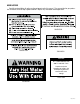
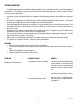
USER NOTICES Carefully read and follow all notices on the equipment and in this manual. They were written for your protection. All notices are to be kept in good condition. Replace any unreadable or damaged labels. 00656.0000 #00831.0000 10044.0000 NOTICE ALL COMPONENTS ARE 200 TO 240 VOLT A.C. Replace only with components listed in the accompaning literature rated for the same voltage 12537.0000 12593.
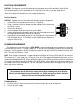
ELECTRICAL REQUIREMENTS CAUTION - The dispenser must be disconnected from the power source until specified in Initial Set-Up. This dispenser requires 2-wire, grounded service rated 208 or 240 volts ac, 40 amp, single phase. (Refer to the dispenser’s dataplate for exact voltage requirement.) Electrical Hook-Up CAUTION – Improper electrical installation will damage electronic components. 1. An electrician must provide electrical service as specified. 2.
INITIAL SET-UP CAUTION - The dispenser must be disconnected from the power source throughout the initial set-up, except when specified in the instructions. 1. Connect the dispenser to the power source and turn on the water supply. 2. The “HEATER” LED will glow for approximately five seconds. During this time, the electronic circuitry will check for a full tank of water. 3. If the tank is not full of water, the refill circuit will energize, indicated by the “REFILL” LED glowing.
TROUBLESHOOTING A troubleshooting guide is provided to suggest probable causes and remedies for the most likely problems encountered. If the problem remains after exhausting the troubleshooting steps, contact the Bunn-O-Matic Technical Service Department. • • • • • • • Inspection, testing, and repair of electrical equipment should be performed only by qualified service personnel. All electronic components have 200-240 volt ac and low voltage dc potential on their terminals.
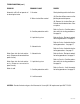
TROUBLESHOOTING (cont.) PROBLEM PROBABLE CAUSE Automatic refill will not operate af- 1. No water ter drawing hot water. REMEDY Check plumbing and shut-off valves. 2. Water strainer/flow control (A) Direction of flow arrow must be pointing towards dispenser. (B) Remove the strainer/flow control and check for obstructions. Clear or replace. 3. Overflow protection switch 4. Liquid level system Refer to Service - Overflow protection switch for testing procedures. See page 16.
TROUBLESHOOTING (cont.) PROBLEM PROBABLE CAUSE REMEDY Water is cold (cont.) 3. Tank heater Refer to Service - Tank heater for testing procedures. See page 19. 4. Temperature control Refer to Service - Electronic controls for testing procedures. See page 12. 5. Dry plug protection Water boils continuously. 1. Temperature control Check connections to Interlock board and sheath of tank temperature probe. Refer to Service - Electronic controls for testing procedures. See page 12.
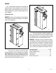
SERVICE This section provides procedures for testing and replacing various major components used in this dispenser should service become necessary. Refer to Troubleshooting for assistance in determining the cause of any problem. Component Access WARNING - Disconnect the dispenser from the power source before the removal of any panel or the replacement of any component.
SERVICE (cont.
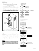
SERVICE (cont.) 9. Check the voltage across the terminals 1 & 4 of the electronic control assembly with a voltmeter. Connect the dispenser to the power source. The indication must be 200 to 240 volts ac for 200 to 240 volt models after a delay of approximately 5 seconds. 10. Touch the screw head end of the probe to the dispenser housing. The indication must be 0. 11. Move the probe away from the dispenser housing.
SERVICE (cont.) If the indicator was on or blinking, the temperature sensor is operating properly, proceed to #7. If the indicator was off, check the sensor connection on the electronic control circuit board and/or replace the temperature sensor and the electronic control assembly. Electronic Controls (cont.) Temperature Control Flow Charts (cont.) H10X THERMOSTAT NOTE - Each temperature sensor is calibrated to an electronic control assembly. Both components MUST be replaced as a set.
5. Install the new temperature sensor into the grommet on the tank lid. Route the wires to the location of the new electronic control assembly. 6. Attach the temperature sensor, overflow tube temperature sensor, and indicator wires to the electronic control assembly. 7. Fasten the new electronic control assembly to its bracket. 8. Reconnect the wires. 9. Review the initial set-up procedures. SERVICE (cont.) Electronic Controls (cont.) 11. Disconnect the dispenser from the power source.
SERVICE (cont.) 3. Securely fasten the new triac assembly to the rear panel in the same relative position as the one removed. Bunn-O-matic recommends tightening the nut to a torque setting of approximately 18 inchpounds. 4. Disconnect the other ends of the old triac assembly wires. 5. Connect the TAN and BLU wires with spade terminals of the new assembly to the electronic control assembly, FIG. 2. 6. Connect the BLU wire with the ring terminal to the tank heater, FIG. 12. 7.
SERVICE (cont.) If voltage was present as described, reconnect the black wire and proceed to #5. If voltage was not present as described, refer to the Wiring Diagrams and check the dispenser wiring harness. Limit Thermostat Limit Thermostat Location: The limit thermostats are located on the tank lid. To test the limit thermostats, access will also be needed to the terminal block located on the side of the dispenser. 5. Check for continuity across the terminals of the limit thermostat.
SERVICE (cont.) Overflow Protection Switch Removal and Replacement: 1. Disconnect the black wires from the overflow protection switch. 2. Remove the nut beneath the copper overflow cup. 3. Remove the entire switch assembly from the cup. 4. Place the new switch assembly into the cup, wires first. Make sure that a gasket is in place around the threaded switch stem.
SERVICE (cont.) If voltage was present as described, proceed to #5. If voltage was not present as described, refer to the Wiring Diagrams and check the dispenser wiring harness. Solenoid Valve Location: The solenoid valve is located within the side of the dispenser on the right side near the bottom. To test the solenoid valve, access will also be needed to the electronic control assembly. 5. Remove both wires from the solenoid valve coil terminals. 6.
SERVICE (cont.) Solenoid Valve (cont.) 5. Lift out the solenoid valve. 6. Remove the two 10-32 slotted-head screws holding the solenoid valve to its mounting bracket. 7. Securely install the new solenoid valve to its mounting bracket. The direction of flow arrow must be pointing towards the tank lid. 8. Attach the solenoid valve and mounting bracket to the component bracket. 9. Securely fasten the water lines to and from the solenoid valve. 10. Reconnect the wires, FIG. 10.
SERVICE (cont.) If voltage is present as described, proceed to #4. If voltage is not present as described, replace the tank heater. Tank Heater Location: 4. Remove the tank heater from the tank lid and inspect it for cracks in the sheath. The tank heater is located in the tank lid. If continuity is present as described, reinstall the tank heater. The tank heater is operating properly. If continuity is not present as described, replace the tank heater. Removal and Replacement: 1.
WIRING DIAGRAM 20 10889 091599