JDF-2 S/N JDF0005473 & UP INSTALLATION & OPERATING MANUAL BUNN-O-MATIC CORPORATION POST OFFICE BOX 3227 SPRINGFIELD, ILLINOIS 62708-3227 PHONE: (217) 529-6601 FAX: (217) 529-6644 To obtain the Illustrated Parts Catalog, visit the Bunn-O-Matic website, at www.bunn.com. This is absolutely FREE, and the quickest way to obtain the catalog. Contact Buun-O-Matic Corporation at 1-800-286-6070 to obtain a paper copy of the required Illustrated Parts Catalog mailed via U.S. Postal Service. 38310.
CONTENTS Introduction & Warranty......................................................................................2 User Notices........................................................................................................3 Initial Set-Up & Electrical Requirements..............................................................4 Plumbing Requirements......................................................................................4 Operating Controls..........................................
USER NOTICES Carefully read and follow all notices on the equipment and in this manual. They were written for your protection. All notices are to be kept in good condition. Replace any unreadable or damaged labels. 00986.0002 27442.0000 00656.0000 12559.0003 33461.
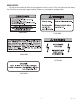
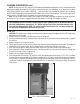
INITIAL SET-UP CAUTION: The dispenser is very heavy! Use care when lifting or moving it. Use at least two people to lift or move the dispenser. Place dispenser on a sturdy counter or shelf able to support at least 150 lbs. (68 kg). The JDF-2 is designed for indoor use only. Set the dispenser on the counter where it will be used. The JDF-2 requires a minimum of 4 inches (102 mm) of air clearance at the rear and 8 inches (203 mm) of air clearance above the dispenser.
PLUMBING REQUIREMENTS (cont) NOTE- At least 18 inches (457 mm) of an FDA approved flexible beverage tubing, such as reinforced braided polyethylene, before the dispenser will facilitate movement to clean the countertop. It can be purchased direct from BUNN-O-MATIC (part number 34325.10_ _ [see Illustrated Parts Catalog for complete part number.]) BUNN-O-MATIC does not recommend the use of saddle valves to install the dispenser.
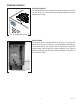
PLUMBING HOOKUP All plumbing connections are located on the rear of the dispenser. For Models prior to the Water Inlet Valve, both the rinse and potable water line must be connected to a water source. P3805 LOADING Models w/Water Inlet Valve Prior to Models w/Water Inlet Valve FIG 2 Plumbing Connections P2656 Frozen Concentrates 1. Thaw the frozen concentrate in a refrigerated 35-40 degrees F (1.6-4.4 degrees C) environment for 36 to 48 hours before use. 2.
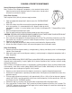
OPERATING CONTROLS Refrigeration Switch The refrigeration switch is located on the top of the dispenser near the left rear corner. This switch controls power to the compressor and the condenser fan motor. FIG 3 Refrigeration Switch P2261 Sanitize Switch The sanitize switch is located behind the drip tray in the lower left corner of the chassis. The drip tray can be removed to provide easy access to the switch.
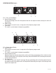
OPERATING CONTROLS (cont.) B B A A C FIG 5 Press and Hold Models A. Product Dispense Switch Pressing and holding switch will initiate product flow from the respective nozzle; releasing the switch will stop the flow. B. Hidden Switch These switches are used to access, change and exit the dispenser program mode. C. Lock Switch This switch is used to lockout the dispensing capabilities. B D D B E E C FIG 6 Portion Control Models B.
DISPENSER USE Press and Hold Models (Refer to Fig 5) 1. Place a cup on the drip tray beneath the desired dispensing nozzle. 2. Press and hold the “Product Dispense” switch until the beverage reaches the desired level, then release. Portion Control Models (Refer to Fig 6) 1. Place a cup on the drip tray beneath the desired dispensing nozzle. 2. Momentarily press the appropriate cup size switch to dispense the beverage.
CLEANING & PREVENTIVE MAINTENANCE General Cleaning and Sanitizing Procedures Note: The Bunn Juice Dispenser incorporates a rinse reminder feature which lights the rinse led on the front panel when it is time to rinse. See dip switch function list to activate this feature. Daily: Rinse Procedure Tools required: 32 oz. (946 ml) minimum empty container 1. Open the refrigerated compartment’s door to access the “DISPENSE/RINSE” Knobs Fig 7. 2.
CLEANING (cont) 6. Select the dispense stations by pressing the “Dispense Switch” for that station. Use the “+/Stop Switch” for portion contol dispensers. The “REFILL” indicator will light and the beeper will sound for the dispense head selected. 7. Once the dispense heads have been selected, press and hold the “Sanitize Switch” for 5 seconds again to initiate the automatic cycle.
CLEANING (cont) Monthly: Clean Condenser Air Filter 1. Remove the condenser air filter located on the rear of the dispenser. 2. Using a water spray, clean the air filter. Annually: Replace Pump Tubing 39689.0000 39687.0000 Tube Kit JDF-2S & JDF-4S Tube Assembly NOTE: High volume applications may require tubing changes every 6 months. 1. Open dispenser door. 2. Remove all product containers and place them in a refrigerated (35-40 degrees F [1.6-4.4 degrees C]) environment.
ADJUSTMENT & OPTIONAL SETTINGS Total Dispense Ratio Set Up Procedure 1. Adjust water flow as described in Water Flow Testing and Adjustment. Record water output setting for later reference on each dispense head. 2. Enter program mode by simultaneously pressing both hidden switches. 3. Press and hold the dispense button, you will hear 5 beeps then two short beeps, continue holding until you hear three short beeps. At this time the dispenser will run product and water for 3 seconds. 4.
ADJUSTMENT & OPTIONAL SETTINGS (cont) Water Flow Testing and Adjustment 1. Enter the “Pump Speed Programming” mode by simultaneously pressing both “Hidden Switches” Fig 5 or Fig 6. Note that the beeper sounds twice and that the “PROGRAM” indicator begins flashing. 2. Place a graduated measuring cup or the large chamber of the empty brixing cup (BUNN-O-MATIC part number 33095.0000) under the appropriate dispense nozzle. 3.
ADJUSTMENT & OPTIONAL SETTINGS (cont) Pump Speed Programming 1. Enter the “Pump Speed Programming” mode by simultaneously pressing both “Hidden Switches”. Note that the beeper sounds twice and that the “PROGRAM” indicator begins flashing. 2. To increase the pump speed, press and hold the right-hand “Hidden Switch” (filled circle) and then momentarily press the “Product Dispense Switch” Fig 5 (“+/STOP Switch” Fig 6, for portion control dispensers).
ADJUSTMENT & OPTIONAL SETTINGS (cont) Dispenser Lockout Dispense and Rinse functions of the dispenser can be electronically locked-out to prevent unauthorized use of the dispenser, while keeping the refrigeration system running. 1. Enter the “Pump Speed Programming” mode by simultaneously pressing both “Hidden Switches”. Note that the beeper sounds twice and that the “PROGRAM” indicator begins flashing. 2. Enter a “Lockout” password as follows: a) Press and hold the left hand “Hidden Switch”.
ADJUSTMENT & OPTIONAL SETTINGS (cont) 3. To remove a dispense station from “Service Lockout,” press and hold either “Hidden Switch” and the desired dispense station “Product Dispense” (“+/Stop”) switch for 10 seconds. 4. At the end of the 10 second period, the beeper will sound a double tone and the dispense position will be enabled. Close the dispenser door.
Dispense Fault List “REFILL” indicator 2 flashes 3 flashes 4 flashes 5 flashes All “REFILL” indicators flash 3 times Beeper 2 beeps 3 beeps 4 beeps 5 beeps 3 beeps Fault Dispense station locked out. DISPENSE/RINSE sensing fault. DISPENSE/RINSE knob mis-positioned. Pump motor stalled/speed sensor inoperative. Dispenser locked out. Cooling Fault List Fault Code “COOLING” DBC display Fault indicator (optional) 8 8 flashes every fault 8 Bath water level low.
Dip Switch Function List Dip Switch Controls Off On 1 “REFILL” indicator when “concentrate out” is detected. Inactive Active 2 Lockout dispense components when “concentrate out” is detected. Inactive Active (Note) 3 Number of positions that can dispense/rinse simultaneously. 3 2 4 Rinse timer Off On 5 Audio feedback during dispenses. On Off 6 Future use. None None Note: When dip switch 2 is in the “on” position, the “REFILL” indicator is active, regardless of dip switch 1 position.
FUNCTION LIST Function # 0 1 2 3 4 101 102 103 104 7 8 9 10 11 12 13 14 15 16 17 18 27 28 29 30 31 32 33 34 50 51 52 53 54 55 75 76 77 78 99 100 Description Enter Password Set Pump 1 RPM (Concentrate A) Set Pump 2 RPM (Concentrate A) Set Pump 3 RPM (Concentrate A) Set Pump 4 RPM (Concentrate A) Set Pump 1 RPM (Concentrate B) Set Pump 2 RPM (Concentrate B) Set Pump 3 RPM (Concentrate B) Set Pump 4 RPM (Concentrate B) Station 1 Large Cup Dispense Time (seconds) Station 1 Medium Cup Dispense Time (seconds) St
TROUBLESHOOTING A troubleshooting guide is provided to suggest probable causes and remedies for the most likely problems encountered. If the problem remains after exhausting the troubleshooting steps, contact the Bunn-O-Matic Technical Service Department. • • • • • • • Inspection, testing, and repair of electrical equipment should be performed only by qualified service personnel. All electronic components have 120-240 volt ac and low voltage dc potential on their terminals.
TROUBLESHOOTING (cont.) PROBLEM PROBABLE CAUSE REMEDY Refrigeration 1. Compressor ON/OFF switch. Check for "ON" position or no continuity - replace switch. 2. Dirty condenser filter or fins. Clean or replace condenser filter. 3. Condenser fan not running. Replace fan motor or check fan blades for obstructions. 4. Compressor relay not activating. Check compressor relay coil for 120vac. NOTE: Aleays check power with coil attached.If no 120vac - replace board. If yes, 120vac - replace relay.
TROUBLESHOOTING (cont.) PROBLEM PROBABLE CAUSE REMEDY Dispense station not working "refill" LED and beep code. 1. Bottle adapter switch membrane A) 3-Beep - Dispense/Rinse sensing fault. A) Dispense/Rinse switch membrane shorted out simultaneously. Check for moisture at 3-pin connector and clean. Apply electrical insulating compound or replace defective switch membrane. B) 4-Beep - Dispense/Rinse knob mis-positioned. B) Dispense/Rinse switch membrane open simultaneously.
TROUBLESHOOTING (cont.) PROBLEM PROBABLE CAUSE REMEDY Dispense station concentrate only Water solenoid Replace solenoid (24vdc) or check wire connection between water valve and main control board. Dispense station water only In rinse position NOTE": Water will dispense for 4 seconds. Rotate knob to dispense position. Dispense starts then stops or "refill" flashes and beeps 5 times. Main control board Check for variable dc voltage when corresponding dispense switch is depressed.
TROUBLESHOOTING (cont.) PROBLEM PROBABLE CAUSE REMEDY Water leak filling drip tray or around dispense deck area 1. Initial fill/setup Some expansion normal. May fill drip tray during initial ice block formation 2. Dispense deck Inspect or replace fittings clamps, o-rings, solenoids and quick disconnect fittings. NOTE: Dispense deck area slopes to drain tube that leads to the drip tray. 3. Water pressure greater than 100psi Install water pressure regulator and reduce to 50 psi. 1.
TROUBLESHOOTING (cont.) PROBLEM PROBABLE CAUSE REMEDY Unit is not working and no beep/light fault codes 1. Step-down transformer. Check for 120/24 vac. If no 24vac reading, replace step-down transformer. 2. Main control board. If 24 vac present and no red LED, replace control board.. Hint: Red LED on main control board is powered from the step-down transformer 24 vac and rectified to 24 vdc by the rectifier. 1. Product viscosity or too cold. Thorough thaw of product before use (35° - 40°) 2.
TROUBLESHOOTING (cont.) PROBLEM PROBABLE CAUSE REMEDY Difficulty brixing and/or weak beverage 1. Pump tubing. Inspect, clean, or replace tubing and pump rotor/rollers for ease of rotation. 2. Bottle adapter assembly leaking NOTE: Leaking water into concentrate bottle during rinse of any station. Replace bottle adapter assembly. 3. Use of portable water pump. A) Follow plumbing requirements for pressure and flow rate. B) Source another portable pump or water supply that meets requirements.
CONDENSER FILTER DRYER SUCTION ACCUMULATOR COMPRESSOR PROCESS TUBE EVAPORATOR COOLANT SCHEMATIC DIAGRAM 28 38310 010406
SCHEMATIC WIRING DIAGRAM BLK WHI/GRN L1 N WHI GRN BLK 1 K1 GRN BLK BLK FLUORESCENT LAMP BALLAST CONDENSOR FAN BLU/BLK MOTOR BRN/BLK WHI WHI BLK LAMP ASSY. TRANSFORMER K1 WHI BLK BLU WHI WHI/BLU EMI FILTER GRY – COMPRESSOR ASSEMBLY 1 K2 10 WHI BRN/BLK RED/BLK GRY WHI BLK RED/BLK WHI/GRN LIMIT THERMOSTAT COMP.
B VIO WHI/VIO ORN WHI/ORN WHI/ORN WHI/VIO RED GRY J5-19 VIO J9-1 SPEED SENSOR #1 WHI/ORN SPEED SENSOR #2 J5-15 J6-1 RED RED J5-10 RED BLK GRN + 24 VDC A J5-5 RED GRY WHI/VIO 1 WHI/VIO ORN WHI/ORN RED GRY 1 RED BLK GRN 8 WHI/ORN VIO BLU ORN YEL WHI/ORN WHI/VIO RED GRY J5-1 PUMP #1 1 30-120 VDC PUMP #2 24 VDC INPUT, 0/5 VDC SWITCHING OUTPUT J6-6 GRY J9-6 WHI/VIO J8-1 C O N T R O L P C B O A R D J6-12 J3-1 J3-2 J1-1 WHI/ORN J1-5 SCHEMATIC WIRING DIAGRAM JDF-2 DISPENSE DECK CIRC
J5-19 J5-15 J5-10 J5-5 J5-1 J6-1 J9-1 J6-6 J9-6 J8-1 C O N T R O L P C B O A R D J3-1 J3-2 J1-1 J1-5 J8-8 J7-1 J7-5 J1-10 J7-16 ORN WHI RED RED/WHI BLK BLU/BLK GRN/BLK BLU ORN/BLK WHI/BLK GRN RED/BLK BLU ORN/BLK WHI/BLK GRN ORN WHI RED GRN/BLK BLU/BLK BLK RED/WHI GRN/WHI BLU/WHI BLK/WHI J4-10 J4-5 J4-1 J1-18 J4-14 J7-10 RED/BLK GRN/WHI BLU/WHI BLK/WHI SCHEMATIC WIRING DIAGRAM JDF-2 CONTROL PANEL CIRCUIT To Switch Unit Assembly 1 1 16 31 RINSE PROGRAM COOLING SHEILD 2 STOP/+
120V MODELS L1 N 50/60 VAC WHI/GRN K1 BLK BRN/BLK GRN BLK BLK 1 ON/OFF BLU/BLK FLUORESCENT LAMP BALLAST BLK WHI WHI LAMP ASSY. TRANSFORMER K1 MOTOR WHI WHI EMI FILTER BLU 24 VAC WHI/BLU BLK CONDENSOR FAN BLU/BLK BLK WHI WHI 24 VDC 120 VAC or 230 VAC COMPRESSOR ASSEMBLY K2 K2 COMP.