BUNN ® T3,T3A T6,T6A DISCONTINUED VERSION The information in this manual is no longer current. OPERATING & SERVICE MANUAL BUNN-O-MATIC CORPORATION POST OFFICE BOX 3227 SPRINGFIELD, ILLINOIS 62708-3227 TELEPHONE: (217) 529-6601 FAX: (217) 529-6644 10145.
CONTENTS Introduction ............................................................................. 2 Warranty .................................................................................. 2 User Notices ............................................................................. 3 Electrical Requirements ........................................................... 4 Plumbing Requirements ........................................................... 4 Initial Set-Up ......................................
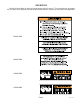
USER NOTICES Carefully read and follow all notices on the equipment and in this manual. They were written for your protection. All notices on the equipment should be kept in good condition. Replace any unreadable or damaged labels. #00831.0000 #00656.0000 #03408.0000 #03409.
ELECTRICAL REQUIREMENTS CAUTION - The brewer must be disconnected from the power source until specified in Initial Set-Up. 120V model brewers require 2-wire, grounded service rated 120 volts ac, 15 amp, single phase, 60 Hz. "A" model brewers require 2-wire, grounded service rated 240 volts ac, 10 amp, single phase, 50 Hz. "B" model brewers require 2-wire, grounded service rated 100 volts ac, 15 amp, single phase, 60 Hz.
INITIAL SET-UP (FILL & HEAT) CAUTION - The brewer must be disconnected from the power source throughout the Initial Set-Up, except when specified in the instructions. 1. Complete the electrical and plumbing instructions prior to starting this procedure. 2. Remove the top panel and check that the thermostat dial is rotated fully counterclockwise to the “OFF” position. 3. Set the delay dial at eight minutes. Replace top panel. Plug in brewer. 4.
INITIAL TIMER ADJUSTMENT (cont.) 10. Install the ferrule and screen in the funnel. Load the funnel with a BUNN® paper filter and approximately four ounces of loose tea leaves. Depress the start button to brew tea and observe the funnel drip out and the dilution streams near the end of the cycle. The dilution stream should stop approximately thirty seconds after the drip out has stopped. 11.
OPERATING CONTROLS (cont.) B. SELECTOR SWITCH (T6 ONLY) Placing the selector switch in the "ON" (left or right) position allows the start switch to activate a timed brew cycle for three gallons of tea. It also selects into which reservoir dilution water will be introduced. This switch should always be in the "OFF" (center) position after a brew cycle or when the brewer is unattended. C. START SWITCH Starts a brew cycle when the ON/OFF or SELECTOR switch is in the "ON" position.
TROUBLESHOOTING A troubleshooting guide is provided to suggest probable causes and remedies for the most likely problems encountered. If the problem remains after exhausting the troubleshooting steps, contact the Bunn-O-Matic Technical Service Department. • • • • • • • Inspection, testing, and repair of electrical equipment should be performed only by qualified service personnel. All electronic components have 120 volt ac and low voltage dc potential on their terminals.
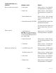
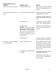
TROUBLESHOOTING (cont.) PROBLEM PROBABLE CAUSE REMEDY Brew cycle will not start (cont.) 5. Start Switch Refer to Service - Start Switch for testing procedures. See page 26 6. Brew Timer Refer to Service - Brew Timer for testing procedures. See page 17 or 18 7. Brew Solenoid Valve Refer to Service - Brew Solenoid Valve for testing procedures. See page 15 8. Internal Flow control (.195 GPM) (A) Direction of flow arrow must be pointing towards brewer.
TROUBLESHOOTING (cont.) PROBLEM PROBABLE CAUSE REMEDY Dilution cycle will not start (cont.) 4. Dilution Solenoid Valve Refer to Service - Dilution Solenoid Valve for testing procedures. See page 21 Inconsistent beverage level in dispenser 1. Internal Flow Control (.195 GPM) (A) Direction of flow arrow must be pointing towards the brewer. (B) Remove the flow control and check for obstruction. Clear or replace. Consistently high or low beverage level in the dispenser 2.
TROUBLESHOOTING (cont.) PROBLEM PROBABLE CAUSE REMEDY Spitting or excessive steaming 1. Lime Build-up CAUTION - Tank and tank components should be delimed regularly depending on local water conditions. Excessive mineral build-up on stainless steel surfaces can initiate corrosive reactions resulting in serious leaks. Inspect tank assembly for excessive lime deposits. Delime as required. 2. Control Thermostat Refer to Service - Control Thermostat for testing procedures.
TROUBLESHOOTING (cont.) PROBLEM PROBABLE CAUSE REMEDY Beverage overflows dispenser 1.Dispenser The dispenser must be completely empty before starting a brew cycle. 2. Brew Timer Refer to Service - Brew Timer for testing procedures. See page 17 or 18 3. Brew Solenoid Valve Remove the Brew Solenoid Valve and clean any obstruction. Rebuild or replace the valve if necessary. See page 15 4. Dilution Timer Refer to Service - Dilution Timer for testing procedures. See page 22 5.
TROUBLESHOOTING (cont.) PROBLEM PROBABLE CAUSE REMEDY Dry tea leaves remain in the funnel 1. Funnel Loading The BUNN® paper filter must be centered in the funnel and the bed of grounds leveled by gently shaking. Brewer is making unusal noises 1. Solenoid(s) The nut on the solenoid(s) must be tight or it will vibrate during operation. 2. Plumbing Lines Plumbing lines should not be resting on the counter top. 3. Water Supply (A) The brewer must be connected to a cold water line.
SERVICE This section provides procedures for testing and replacing various major components used in this brewer should service become necessary. Refer to Troubleshooting for assistance in determining the cause of any problem. WARNING - Inspection, testing, and repair of electrical equipment should be performed only by qualified service personnel.
SERVICE (cont.) BREW SOLENOID VALVE If continuity is present as described, reconnect the white/violet from the switch and white/green wire from the brew timer. If continuity is not present as described, replace the solenoid valve. 6. Check the solenoid valve for coil action. Connect the brewer to the power source.
SERVICE (cont.) BREW SOLENOID VALVE (cont.) BRN/BLK to Selector Switch WHI/BLU to Dilution Timer TL4 YEL to Selector Switch WHI/BLU to Dilution Timer TL4 WHI/GRN to BREW Timer TL4 WHI/VIO to Dilution Solenoid WHI/VIO to Brew Solenoid WHI/VIO to Brew Timer TL1 WHI/GRN to Brew Timer TL4 WHI/VIO to Brew Timer TL1 DILUTION SOLENOID LT RESERVOIR DILUTION SOLENOID RT RESERVOIR DILUTION SOLENOID BREW SOLENOID BREW SOLENOID T3 T6 FIG.
SERVICE (cont.) Wiring Diagrams and check the wiring harness. BREW TIMER 5. Check the voltage across terminals TL1 and TL4 with a voltmeter when the ON/OFF or SELECTOR switch is in the “ON” (T3 left, T6 left or right) position and the start switch is momentarily placed in the lower position. Connect the brewer to the power source. The indication must be: a) 120 volts ac for two wire 120 volt models for approximately twenty seconds and then return to its previous indication.
SERVICE (cont.) DIGITAL BREW TIMER (Late Models) If voltage is not present as described, refer to the Wiring Diagrams and check the brewer wiring harness. 6. With a voltmeter, check the voltage across terminals TL1 and TL4 when the "ON/OFF" switch is in the "ON" position. Connect the brewer to the power source. The indication must be 0 volts. If voltage is as described, proceed to #7. If voltage is not as described, disconnect the brewer from the power source and replace the timer. 7.
SERVICE (cont.) DIGITAL BREW TIMER (Late Models)(cont.) NOTE: When brewing coffee, volume will decrease due to absorption by the coffee grounds. 1. Modifying brew volumes. To modify a brew volume, first check that the SET/LOCK switch is in the “SET” position on the circuit board. To increase a brew volume, place the ON/OFF switch in the “ON” position, press and hold the START switch until three clicks are heard. Release the switch and press it again one or more times.
SERVICE (cont.) 240 volt two wire models when the control thermostat is turned fully clockwise. Connect the brewer to the power source. The indication must be: a) 120 volts ac for two wire 120 volt models. b) 240 volts ac for two wire 240 volt models. c) 100 volts ac for two wire 100 volt models. 8. Disconnect the brewer from the power source. CONTROL THERMOSTAT If voltage is present as described, reinstall the capillary tube into the tank to the line 4.
SERVICE (cont.) DILUTION SOLENOID VALVE(S) main for the approximate setting on the dilution dial, then return to its previous indication. If voltage is present as described, proceed to #4. If voltage is not present as described, refer to the Wiring Diagrams and check the wiring harness. 4. Remove both wires from the coil and check for continuity across the coil terminals. If continuity is present as described, reconnect the white/blue and white/violet wires and proceed to #5.
If continuity is present as described, reconnect the wires to terminals TL3, TL4, & TL5 of the timer board and proceed to #5. If continuity is not present as described, refer to the Wiring Diagrams and check the wiring harness. SERVICE (cont.) DILUTION TIMER FIG. 11 DILUTION TIMER P2207.40 Location: The dilution timer is located inside the hood on the right side. It consists of the dial plate with two dials and circuit board. Test Procedure: 1.
SERVICE (cont.) LIMIT THERMOSTAT 4. Remove the blue/black wire from the limit thermostat. 5. With a voltmeter, check the voltage across the exposed terminal of the limit thermostat and the white wire or red wire on the tank heater. Connect the brewer to the power source. The indication must be: a) 120 volts ac for two wire 120 volt models. b) 240 volts ac for two wire 240 volt models. c) 100 volts ac for two wire 100 volt models. 6. Disconnect the brewer from the power source.
SERVICE (cont.) ON/OFF SWITCH (T3 W/OUT HALF BATCH) or SELECTOR SWITCH (T3 W/HALF BATCH and T6 BREWERS) 6. Check for continuity across the center and end terminals of the top row when the switch is in the “ON” (left) position. If continuity is present as described, replace the wires, the switch is operating properly. If continuity is not present as described, replace the switch. T3 Brewers W/Half Batch Option 1. Disconnect the brewer from the power source. 2.
SERVICE (cont.) ON/OFF SWITCH (T3 W/OUT HALF BATCH) or SELECTOR SWITCH (T3 W/HALF BATCH and T6 BREWERS)(cont.) T6 Brewers 1. Disconnect the brewer from the power source. 2. Remove the black wire from the top center switch terminal. 3. With a voltmeter, check the voltage across the black wire removed from the selector switch and the white wire or red wire on the tank heater. 4. Connect the brewer to the power source.The indication must be: a) 120 volts ac for two wire 120 volt models.
SERVICE (cont.) START SWITCH If continuity is present as described, reconnect the wires, the switch is operating properly. If continuity is not present as described, replace the switch. Removal and Replacement: 1. Remove the wires from the switch terminals. 2. Compress the clips inside the hood and gently push the switch through the opening. 3. Push the new switch into the opening and spread the clips to hold the switch captive in the hood. 4. Refer to Fig. 18 when reconnecting the wires. P1833.
SERVICE (cont.) TANK HEATER FIG. 19 TANK HEATER P1833 Location: The tank heater is located inside the tank and secured to the tank lid. Test Procedures: 1. Disconnect the brewer from the power supply. 2. With a voltmeter, check the voltage across the black and white wires on 100 volt and 120 volt models or the black and red wires for 240 volt models. Connect the brewer to the power source. The indication must be: a) 120 volts ac for two wire 120 volt models . b) 240 volts ac for two wire 240 volt models.
Page 28 10145 072600
Page 29 10145 072600
Page 30 10145 072600