TB3 TB3-LP OPERATING & SERVICE MANUAL BUNN-O-MATIC CORPORATION POST OFFICE BOX 3227 SPRINGFIELD, ILLINOIS 62708-3227 PHONE: (217) 529-6601 FAX: (217) 529-6644 37235.0000D 05/06 ©2004 Bunn-O-Matic Corporation www.bunn.
CONTENTS Introduction ..................................................................... 2 Warranty .......................................................................... 2 User Notices..................................................................... 3 Electrical & Plumbing Requirements ............................... 4 Initial Set-Up .................................................................... 5 Adjusting Brew Volumes ..................................................
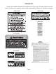
USER NOTICES Carefully read and follow all notices on the equipment and in this manual. They were written for your protection. All notices on the equipment should be kept in good condition. Replace any unreadable or damaged #00831.0000 #00656.0000 #06064.0000 WARNING • FILL WATER TANK BEFORE ENERGIZING • DO NOT OVERLOAD CIRCUIT • KEEP AWAY FROM COMBUSTIBLES • DO NOT DEFORM PLUG OR CORD SEE INSTRUCTIONS • FAILURE TO COMPLY RISKS EQUIPMENT DAMAGE, FIRE OR SHOCK #37881.
ELECTRICAL REQUIREMENTS CAUTION - The brewer must be disconnected from the power source until specified in Initial Set-Up. 120V model brewers require 2-wire, grounded service rated 120 volts ac, 15 amp, single phase, 60 Hz. "A" model brewers require 2-wire, grounded service rated 230 volts ac, 10 amp, single phase, 50 Hz. "B" model brewers require 2-wire, grounded service rated 100 volts ac, 15 amp, single phase, 60 Hz.
INITIAL SET-UP CAUTION - The brewer must be disconnected from the power source throughout the initial set-up, except when specified in the instructions. 1. Remove the top lid from the brewer. 2. Rotate the control thermostat knob fully counterclockwise to the "OFF" position and replace the top lid. 3. Set the delay knob of the timer on the right side of the hood at eight minutes and the dilution knob of the timer on the right side of the hood at three minutes and forty-five seconds. 4.
INITIAL SET-UP (cont.) 21. When all water stops flowing, check the water volume in the dispenser. It should be 396 ounces. 22. If not, unplug the brewer and remove the top lid. 23. Adjust the dilution knob of the timer on the right side of the hood as required. Replace the top lid, plug in the brewer, start, and measure another brew cycle. 24. Repeat steps 20-23 until the proper water volume is achieved. 25. Return the delay knob of the timer on the right side of the hood to eight minutes.
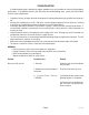
AUTO SWEETENER SET-UP CAUTION - The brewer must be disconnected from the power source throughout the Initial Set-Up, except when specified in the instructions. 1. Remove the top lid and rear panel. 2. Make sure the brewer water supply is off. 3. Connect sweetener hose from the bag in a box delivery system to the rear fitting marked "Sweetener" . IMPORTANT - System delivery pressure must be regulated between 30-40 psi. System also needs to deliver product for at least 4 minutes without shutting off.
CLEANING CAUTION - CLEAN AND SANITIZE YOUR ICED TEA BREWER DAILY 1. Remove and thoroughly clean the entire brew funnel. The funnel tip and screen must be free from any tea particles or residue. Reassemble the funnel. 2. Place the ON/OFF switch in the "OFF" position. Remove and thoroughly rinse the sprayhead. The holes must be open and clear of any mineral deposits. Wipe the sprayhead panel clean with a damp cloth. 3.
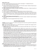
TROUBLESHOOTING A troubleshooting guide is provided to suggest probable causes and remedies for the most likely problems encountered. If the problem remains after exhausting the troubleshooting steps, contact the Bunn-O-Matic Technical Service Department. • • • • • • • Inspection, testing, and repair of electrical equipment should be performed only by qualified service personnel. All electronic components have 120 - 240 volt ac and low voltage dc potential on their terminals.
TROUBLESHOOTING (cont.) PROBLEM PROBABLE CAUSE REMEDY Brew cycle will not start (cont.) 4. ON/OFF Switch Refer to Service - ON/OFF Switch for testing. See page 24 5. Start Switch Refer to Service - Start Switch for testing procedures. See page 23 6. Brew Timer Refer to Service - Brew Timer for testing procedures. See page 18 7. Brew Solenoid Valve Refer to Service - Brew Solenoid Valve for testing procedures. See page 16 8. Internal Flow control (.
TROUBLESHOOTING (cont.) PROBLEM PROBABLE CAUSE REMEDY Dilution cycle will not start (cont.) 4. Dilution Solenoid Valve Refer to Service - Dilution Solenoid Valve for testing procedures. See page 20 Inconsistent beverage level in dispenser 1. Internal Flow Control (.195 GPM) (A) Direction of flow arrow must be pointing towards the check valve. (B) Remove the flow control and check for obstruction. Clear or replace. Consistently high or low beverage level in the dispenser 2.
TROUBLESHOOTING (cont.) PROBLEM PROBABLE CAUSE REMEDY Spitting or excessive steaming 1. Lime Build-up CAUTION - Tank and tank components should be delimed regularly depending on local water conditions. Excessive mineral build-up on stainless steel surfaces can initiate corrosive reactions resulting in serious leaks. Inspect tank assembly for excessive lime deposits. Delime as required. 2. Control Thermostat Refer to Service - Control Thermostat for testing procedures.
TROUBLESHOOTING (cont.) PROBLEM PROBABLE CAUSE REMEDY Beverage overflows dispenser 1. Dispenser The dispenser must be completely empty before starting a brew cycle. 2. Brew Timer Refer to Service - Brew Timer for testing procedures. See page 18 3. Brew Solenoid Valve Remove the Brew Solenoid Valve and clean any obstruction. Rebuild or replace the valve if necessary. See page 16 4. Dilution Timer Refer to Service - Dilution Timer for testing procedures. See page 21 5.
TROUBLESHOOTING (cont.) PROBLEM PROBABLE CAUSE REMEDY Dry tea leaves remain in the funnel 1. Funnel Loading The BUNN® paper filter must be centered in the funnel and the bed of grounds leveled by gently shaking. Brewer is making unusual noises 1. Solenoid(s) The nut on the solenoid(s) must be tight or it will vibrate during operation. 2. Plumbing Lines Plumbing lines should not be resting on the counter top. 3. Water Supply (A) The brewer must be connected to a cold water line.
SERVICE This section provides procedures for testing and replacing various major components used in this brewer should service become necessary. Refer to Troubleshooting for assistance in determining the cause of any problem. WARNING - Inspection, testing, and repair of electrical equipment should be performed only by qualified service personnel.
SERVICE (cont.
SERVICE (cont.) thermostat is turned fully clockwise. Connect the brewer to the power source. The indication must be: a) 120 volts ac for two wire 120 volt models. b) 230 volts ac for two wire 230 volt models. c) 100 volts ac for two wire 100 volt models. 8. Disconnect the brewer from the power source. CONTROL THERMOSTAT TIC MA -O- 5 NN 335 4 BU P/N 5 If voltage is present as described, reinstall the capillary tube into the tank to the line 4.
SERVICE (cont.
SERVICE (cont.) DIGITAL BREW TIMER (cont.) To increase a brew volume, place the ON/OFF switch in the "ON" position, press and hold the START switch until three clicks are heard. Release the switch and press it again one or more times. (Failure to release the switch within two seconds after the third click causes the volume setting to be aborted and previous volume setting will remain in memory.) Each time the switch is pressed, two seconds are added to the brew time period.
SERVICE (cont.
SERVICE (cont.) If continuity is present as described, reconnect the wires to terminals TL3, TL4, & TL5 of the timer board and proceed to #5. If continuity is not present as described, refer to the Wiring Diagrams and check the wiring harness. DILUTION TIMER TIC MA -O- 5 NN 335 4 BU P/N 5 6 7 3 6 5 7 8 2 6 4 3 S UTE MIN LAY DE 1 S UTE MIN ON UTI DIL FIG. 10 DILUTION TIMER P3040 Location: The dilution timer is located inside the hood on the right side.
SERVICE (cont.
Page 23
Page 24
Page 25
If continuity is not present as described, replace the solenoid valve. SERVICE (cont.) SWEETNER SOLENOID VALVE 5. Check the solenoid valve for coil action. Connect the brewer to the power source, place the UNSWEET/OFF/SWEET switch in the “SWEET” position and momentarily place the start switch in the lower position and release.
SERVICE (cont.) TANK HEATER FIG.
SCHEMATIC WIRING DIAGRAM TB3, TB3B, TB3-LP OPTIONAL READY INDICATOR BLU L1 BLU/BLK N GRN SWITCH & THERMOSTAT LIMIT THERMOSTAT BLK BLK BLK WHI TANK HEATER WHI WHI ON/OFF SWITCH "KEEP WARM" HEATER WHI BLK WHI/VIO DILUTION WHI/VIO WHI/VIO SOL 2 WHI/GRN SOL 1 BREW 100 VOLTS AC 120 VOLTS AC 2 WIRE SINGLE PHASE BREW TIMER DILUTION TIMER 5 4 3 2 1 5 4 3 2 1 WHI/VIO WHI WHI/BLU WHI/ORN WHI/YEL WHI START SWITCH RED/BLK GRN 37234.
SCHEMATIC WIRING DIAGRAM TU3, TB3 W/SWEETENER READY INDICATOR BLU/BLK BLK SELECTOR SWITCH UNSWEET/OFF/SWEET WHI/VIO WHI WHI/BLU WHI WHI/BLU BRN/WHI WHI/ORN WHI/YEL 120 VOLTS AC 2 WIRE SINGLE PHASE 27432.
Page 30
Page 31