TB3Q TB3Q-LP OPERATING & SERVICE MANUAL BUNN-O-MATIC CORPORATION POST OFFICE BOX 3227 SPRINGFIELD, ILLINOIS 62708-3227 PHONE: (217) 529-6601 FAX: (217) 529-6644 37236.0000C 05/05 ©2004 Bunn-O-Matic Corporation www.bunnomatic.
CONTENTS User Notices .................................................................... 3 Electrical & Plumbing Requirements ............................... 4 Initial Set-Up .................................................................... 5 Auto Sweetener Set-Up .................................................... 6 Adjusting Brew Volumes .................................................. 7 Operating Controls ........................................................... 8 Cleaning .....................
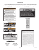
USER NOTICES Carefully read and follow all notices on the equipment and in this manual. They were written for your protection. All notices on the equipment should be kept in good condition. Replace any unreadable or damaged labels. #00831.0000 #37881.0000 ! WARNING Fill water tank before turning - on thermostat or connecting appliance to power source. Use only on a properly protected circuit capable of the rated load. Electrically ground the chassis. Follow national/local electrical codes.
ELECTRICAL REQUIREMENTS CAUTION - The brewer must be disconnected from the power source until specified in Initial Set-Up. 120V model brewers require 2-wire, grounded service rated 120 volts ac, 15 amp, single phase, 60 Hz. "A" model brewers require 2-wire, grounded service rated 230 volts ac, 10 amp, single phase, 50 Hz. "B" model brewers require 2-wire, grounded service rated 100 volts ac, 15 amp, single phase, 60 Hz.
INITIAL SET-UP CAUTION - The brewer must be disconnected from the power source throughout the Initial Set-Up, except when specified in the instructions. 1. Remove the top lid from the brewer. 2. Rotate the control thermostat knob fully counterclockwise to the "OFF" position and replace the top lid. 3. Insert an empty funnel into the funnel rails. 4. Place an empty dispenser on the brewer base. Be prepared to empty the dispenser during these initial steps. 5.
AUTO SWEETENER SET-UP CAUTION - The brewer must be disconnected from the power source throughout the Initial Set-Up, except when specified in the instructions. 1. Remove the top lid and both rear panels. 2. Make sure the brewer water supply is off. 3. Connect sweetener hose from the bag in a box delivery system to the rear fitting marked "Sweetener" . IMPORTANT - System delivery pressure must be regulated between 30-40 psi. System also needs to deliver product for at least 4 minutes without shutting off.
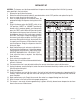
ADJUSTING BREW VOLUMES CAUTION - Disconnect the power source from the brewer prior to the removal of any panel for the replacement or adjustment of any component. NOTE: Prior to setting or modifying batch sizes, check that the brewer is connected to water supply, the tank is properly filled, and a funnel and server are in place. 1. Modifying batch sizes. To modify a batch volume, first check that the SET/LOCK switch is in the “SET” position on the circuit board. To increase a batch size.
OPERATING CONTROLS A. ON/OFF Switch ON - Placing the switch in the left position allows the start switch to activate a timed brew cycle for three gallons of tea. OFF - Placing the switch in the right position stops the brew cycle. Stopping a brew cycle after it has been started will not stop the flow of water into the funnel until the tank syphons down to its proper level. The switch should always be placed in this position after a brew cycle and whenever the brewer is unattended. B.
TEA BREWING 1. Begin each brew cycle with a clean empty brew funnel and server. (Be sure the server lid doesn’t interfere with the flow of dilution water.) 2. Insert a BUNN® filter into the funnel. 3. Pour the packet of loose fresh tea leaves into the filter. Approximately three to five ounces is recommended for three gallons of beverage. 4. Level the bed of tea leaves by gently shaking. 5. Slide the funnel into the funnel rails until it stops. 6. Place the ON/OFF switch in the “ON” position.
TROUBLESHOOTING A troubleshooting guide is provided to suggest probable causes and remedies for the most likely problems encountered. If the problem remains after exhausting the troubleshooting steps, contact the Bunn-O-Matic Technical Service Department. • • • • • • • Inspection, testing, and repair of electrical equipment should be performed only by qualified service personnel. All electronic components have 120-240 volt ac and low voltage dc potential on their terminals.
TROUBLESHOOTING (cont.) PROBLEM PROBABLE CAUSE REMEDY Brew cycle will not start (cont.) 6. Brew Timer Refer to Service - Brew Timer for testing procedures. See page 17 7. Brew Solenoid Valve Refer to Service - Brew Solenoid Valve for testing procedures. See page 16 1. Limit Thermostat CAUTION - Do not eliminate or bypass limit thermostat or thermal cut-off. Use only BOM replacement part #29329.0001 Refer to Service - Limit Thermostat for testing procedures. See page 20. 2.
TROUBLESHOOTING (cont.) PROBLEM Consistently high or low beverage level in the dispenser PROBABLE CAUSE REMEDY 1. Strainer/Flow Control (.750GPM) (A) Direction of flow arrow must be pointing upwards in the brewer. (B) Remove the strainer/flow control and check for obstructions. Clear or replace. Spitting or excessive steaming 1. Lime Build-up CAUTION - Tank and tank components should be delimed regularly depending on local water conditions.
TROUBLESHOOTING (cont.) PROBLEM Dripping from sprayhead PROBABLE CAUSE 1. Syphon System REMEDY The brewer must be level or slightly lower in front to syphon properly. 2. Lime Build-up CAUTION - Tank and tank components should be delimed regularly depending on local water conditions. Excessive mineral build-up on stainless steel surfaces can initiate corrosive reactions resulting in serious leaks. Inspect the tank assembly for excessive lime deposits. Delime as required. 3.
TROUBLESHOOTING (cont.) PROBLEM PROBABLE CAUSE REMEDY Weak beverage (cont.) 4. Funnel Loading The BUNN® paper filter must be centered in the funnel and the bed of tea leaves leveled by gentle shaking. 5. Water Temperature Place an empty funnel on an empty dispenser beneath the sprayhead. Initiate a brew cycle and check the water temperature immediately below the sprayhead with a thermometer. The reading should not be less than 200°F (93°C).
SERVICE This section provides procedures for testing and replacing various major components used in this brewer should service become necessary. Refer to Troubleshooting for assistance in determining the cause of any problem. WARNING - Inspection, testing, and repair of electrical equipment should be performed only by qualified service personnel.
SERVICE (cont.) BREW SOLENOID VALVE If continuity is not present as described, replace the solenoid valve. 6. Check the solenoid valve for coil action. Connect the brewer to the power source. With ON/OFF switch in the "ON" position ("UNSWEET" position for brewers with sweetener option), press START switch and listen carefully in the vicinity of the solenoid valve for a "clicking" sound as the coil magnet attracts. 7. Disconnect the brewer from the power source.
SERVICE (cont.) DIGITAL BREW TIMER 6. With a voltmeter, check the voltage across terminals TL1 and TL4 when the "ON/OFF" switch is in the "ON" position. Connect the brewer to the power source. The indication must be 0 volts. If voltage is as described, proceed to #7. If voltage is not as described, disconnect the brewer from the power source and replace the timer. 7. With a voltmeter, check the voltage across terminals TL1 and TL4 when the "ON/OFF" switch is in the "ON" position.
SERVICE (cont.) DIGITAL BREW TIMER (cont.) To increase a brew volume, place the ON/OFF switch in the “ON” position, press and hold the START switch until three clicks are heard. Release the switch and press it again one or more times. (Failure to release the switch within two seconds after the third click causes the volume setting to be aborted and previous volume setting will remain in memory.) Each time the switch is pressed, two seconds are added to the brew time period.
SERVICE (cont.) CONTROL THERMOSTAT brewer to the power source. The indication must be: a) 120 volts ac for two wire 120 volt models. b) 230 volts ac for two wire 230 volt models. c) 100 volts ac for two wire 100 volt models. 8. Disconnect the brewer from the power source. If voltage is present as described, reinstall the capillary tube into the tank to the line 5.5" above the bulb, the control thermostat is operating properly. If voltage is not present as described, replace the thermostat.
SERVICE (cont.) LIMIT THERMOSTAT 5. With a voltmeter, check the voltage across the exposed terminal of the limit thermostat and the white wire from the power cord or the red wire from the power connector. Connect the brewer to the power source. The indication must be: a) 120 volts ac for two wire 120 volt models. b) 230 volts ac for two wire 230 volt models. c) 100 volts ac for two wire 100 volt models. 6. Disconnect the brewer from the power source.
SERVICE (cont.) ON/OFF SWITCH 5. Disconnect the brewer from the power source. If voltage is present as described, proceed to #6. If voltage is not present as described, refer to the Wiring Diagrams and check the wiring harness. 6. Check for continuity across the center and end terminals of the top row when the switch is in the “ON” position. If continuity is present as described, replace the wires, the switch is operating properly. If continuity is not present as described, replace the switch.
SERVICE (cont.) START SWITCH If continuity is present as described, reconnect the wires, the switch is operating properly. If continuity is not present as described, replace the switch. Removal and Replacement: 1. Remove the wires from the switch terminals. 2. Compress the clips inside the hood and gently push the switch through the opening. 3. Push the new switch into the opening and spread the clips to hold the switch captive in the hood. 4. Refer to Fig. 13 when reconnecting the wires.
SERVICE (cont.) UNSWEET/OFF/SWEET SWITCH (Sweetner Option) 5. Disconnect the black and white wires from the center terminals. 6. Disconnect the brown/white and white/violet wires from the right side terminals. 7. Check for continuity across the center and right terminals in rows one through four when the switch is in the "SWEET” position. If continuity is present as described, replace the wires on the right side and proceed to #8. If continuity is not present as described, replace the switch. 8.
If continuity is not present as described, replace the solenoid valve. SERVICE (cont.) SWEETNER SOLENOID VALVE 5. Check the solenoid valve for coil action. Connect the brewer to the power source, place the UNSWEET/OFF/SWEET switch in the “SWEET” position and momentarily place the start switch in the lower position and release.
SERVICE (cont.) TANK HEATER NOTE: If the tank heater remains unable to heat, remove and inspect heater for cracks in the sheath. P3047 FIG. 18 TANK HEATER Location: The tank heater is located inside the tank and secured to the tank lid. Test Procedures: 1. Disconnect the brewer from the power supply. 2. With a voltmeter, check the voltage across the black and white wires on 100 volt and 120 volt models or the black and red wires for 230 volt models. Connect the brewer to the power source.
SCHEMATIC WIRING DIAGRAM TB3Q (OPTIONAL) READY INDICATOR BLU/BLK BLK L1 LIMIT THERMOSTAT GREEN N SW. & THERMOSTAT BLK TANK HEATER BLK WHI BLU/BLK WHI WHI "KEEP WARM HEATER" SW1 WHI/VIO BLK 1 BREW 2 3 TIMER 4 5 120 VOLTS AC 2 WIRE SINGLE PHASE WHI WHI SOL SW2 WHI/VIO WHI WHI/ORA WHI/GRN WHI/YEL 37234.
SCHEMATIC WIRING DIAGRAM TB3QA GRN/YEL L1 SW. & THERMOSTAT LIMIT THERMOSTAT BLK BLU/BLK L2 THERMAL FUSE BLK THERMAL FUSE RED TANK HEATER WHI WHI SW1 BLK "KEEP WARM" HEATER WHI/VIO 230 VOLTS AC 2 WIRE SINGLE PHASE SOL WHI/GRN BREW TIMER RED WHI/VIO RED WHI/ORN WHI/GRN WHI/YEL SW2 37234.