TB3/TB6 Series Including: TB3; TB3-LP; TB3Q; TB3Q-LP; TB6; TB6Q STARTING WITH SERIAL NUMBER: TU00020000 SERVICE & REPAIR MANUAL BUNN-O-MATIC CORPORATION POST OFFICE BOX 3227 SPRINGFIELD, ILLINOIS 62708-3227 PHONE: (217) 529-6601 FAX: (217) 529-6644 41722.
BUNN-O-MATIC COMMERCIAL PRODUCT WARRANTY Bunn-O-Matic Corp. (“BUNN”) warrants equipment manufactured by it as follows: 1) All equipment other than as specified below: 2 years parts and 1 year labor. 2) Electronic circuit and/or control boards: parts and labor for 3 years. 3) Compressors on refrigeration equipment: 5 years parts and 1 year labor.
Contents Trouble Shooting............................................................................................................... 4 Component Acess .......................................................................................................... 10 Control Thermostat......................................................................................................... 10 Limit Thermostat........................................................................................................
TROUBLESHOOTING A troubleshooting guide is provided to suggest probable causes and remedies for the most likely problems encountered. If the problem remains after exhausting the troubleshooting steps, contact the Bunn-O-Matic Technical Service Department. • • • • • • • Inspection, testing, and repair of electrical equipment should be performed only by qualified service personnel. All electronic components have 120 volt ac and low voltage dc potential on their terminals.
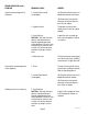
TROUBLESHOOTING (cont.) PROBLEM PROBABLE CAUSE REMEDY Brew cycle will not start (cont.) 3. ON/OFF Switch Refer to Service - ON/OFF Switch for testing. 4. Start Switch Refer to Service - Start Switch for testing procedures. 5. Timer Refer to Service - Timer for testing procedures. 6. Solenoid Valve Refer to Service - Solenoid Valve for testing procedures. 7. Water strainer/flow control (If equipped) (A) Direction of flow arrow must be pointing towards brewer.
TROUBLESHOOTING (cont.) PROBLEM PROBABLE CAUSE REMEDY Inconsistent beverage level in dispenser 1. Strainer /flow control (If equipped) (A) Direction of flow arrow must be pointing towards the brewer. (B) Remove the strainer/flow control and check for obstruction. Clear or replace. Consistently low beverage level in the dispenser 2. Syphon System The brewer must be level or slightly lower in front to syphon properly. 3.
TROUBLESHOOTING (cont.) PROBLEM PROBABLE CAUSE REMEDY Spitting or excessive steaming (cont.) 2. Control Thermostat Refer to Service - Control Thermostat for testing procedures. Dripping from sprayhead 1. Syphon System The brewer must be level or slightly lower in front to syphon properly. 2. Lime Build-up CAUTION - Tank and tank components should be delimed regularly depending on local water conditions.
TROUBLESHOOTING (cont.) PROBLEM PROBABLE CAUSE REMEDY Weak beverage 1. Filter Type BUNN® paper filters must be used for proper extraction. 2. Coffee Grind A fine or drip grind must be used for proper extraction. 3. Sprayhead A six-hole stainless steel sprayhead must be used for proper extraction. 4. Funnel Loading The BUNN® paper filter must be centered in the funnel and the bed of ground leveled by gentle shaking. 5.
TROUBLESHOOTING (cont.) PROBLEM Brewer is making unusal noises (cont.) PROBABLE CAUSE REMEDY 4. Tank Heater Remove and clean lime off the tank heater.
SERVICE This section provides procedures for testing and replacing various major components used in this brewer should service become necessary. Refer to Troubleshooting for assistance in determining the cause of any problem. CONTROL THERMOSTAT WARNING - Inspection, testing, and repair of electrical equipment should be performed only by qualified service personnel.
SERVICE (cont.) CONTROL THERMOSTAT (cont.) source. The indication must be: a) 120 volts ac for two wire 120 volt models. b) 200 to 230 volts ac for two wire 200 volt or 230 volt models. 8. Disconnect the brewer from the power source. If voltage is present as described, reinstall the capillary tube into the tank to the line 4.5" above the bulb, the control thermostat is operating properly. If voltage is not present as described, replace the thermostat. Removal and Replacement: 1.
SERVICE (cont.) LIMIT THERMOSTAT If continuity is present as described, the limit thermostat is operating properly. If continuity is not present as described, replace the limit thermostat. Removal and Replacement: 1. Remove all wires from limit thermostat terminals. 2. Carefully slide the limit thermostat out from under the retaining clip and remove limit thermostat. 3. Carefully slide the new limit thermostat into the retaining clip. 4. Refer to the schematics when reconnecting the wires.
SERVICE (cont.) TANK HEATER HEATER RESISTANCE 1680W-120V 7.9 - 9.2 1680W-100V 5.5 -6.4 1680W-230V 29.0 -33.7 TERMINAL TO SHEATH - INFINITE (OPEN) If resistance is not present as described, replace the tank heater. NOTE- If any resistance is read between sheath and either terminal, remove and inspect heater for cracks in the sheath. FIG. 13-1 TANK HEATER Location: The tank heater is located inside the tank and secured to the tank lid. Test Procedures: 1. Disconnect the brewer from the power supply. 2.
SERVICE (cont.) LIGHTED ON/OFF SWITCH (TB3/TB3Q) Removal and Replacement: 1. Remove the wires from the switch terminals. 2. Compress the clips inside the hood and gently push the switch through the opening. 3. Push the new switch into the opening and spread the clips to hold the switch captive in the hood. 4. Refer to FIG. 14-2 when reconnecting the wires. P/N 37080.0000 Orange light FIG.
SERVICE (cont.) ON/OFF SWITCH-TB6/Q (Sweetner ½ Batch Option-TB3/Q) WHI/VIO BLACK PINK optional ½ batch P/N 03356.0003 Non Lighted GRAY Optional ½ batch FIG. 15-1 NON LIGHTED ON/OFF SWITCH FULL/OFF/HALF-TB3/TB3Q Location: The switch is located on the front control panel. WHI/VIO WHITE Test Procedure: 1. Disconnect the brewer from the power source. 2. Disconnect the wires from switch terminals. 3.
SERVICE (cont.) START SWITCHES WHI/YEL to Timer T5 P/N 37079.0000 Non Lighted WHI/ORN to Timer T3 P/N 37080.0001 Green ready light FIG. 16-1 START SWITCHES P/N 37079.0000 Location: The start switch is located in the front of the hood, above and to the right of the brew funnel. Test Procedure: 1. Disconnect the brewer from the power source. 2. Remove the wires from all four terminals. 3. Check for continuity across the two terminals on the right side of the switch when it is held in the lower position.
SERVICE (cont.) INLET VALVES three wire 120/240 volt models. b) 200 to 230 volts ac for two wire 200 or 230 volt models. 7. Disconnect the brewer from the power source, If voltage is present as described, proceed to #8 If voltage is not present as described, refer to Wiring Diagrams and check brewer wiring harness. 8. Check for continuity across the solenoid terminals. If continuity is present as described, reconnect the white and black wire from the timer.
SERVICE (cont.) BREW/DILUTION TIMER (TB3 & TB6) If voltage is present as described, the timer is operating properly. If voltage is not present as described, disconnect the brewer from the power source and replace the timer. Removal and Replacement: 1. Remove the two #6-32 screws, lock washers and spacers securing timer to bracket. 2. Disconnect all wires from the timer. 3. Refer to schematic and reconnect wires. 4. Install new timer to bracket with the two #6-32 screws, lock washers and spacers. 5.
SERVICE (cont.) BREW/DILUTION TIMER (TB3 & TB6) (cont.) FIG.
SERVICE (cont.) DIGITAL BREW TIMER (TB3Q & TB6Q) to the power source, turn on the "ON/OFF" switch and press the "START" switch. The indication must be as follows: a) 120 volts ac for two wire 120 volt models. b) 200 to 230 volts ac on two wire 200 volt or 230 volt models. If voltage is not present as described, refer to the Wiring Diagrams and check the wiring harness to the start switch. If start voltage is present as described (but no output voltage), replace the timer. FIG.
SERVICE (cont.) DIGITAL BREW TIMER (TB3Q & TB6Q) (cont.) FIG.
SCHEMATIC WIRING DIAGRAM TB3Q (OPTIONAL) READY INDICATOR BLU/BLK BLK L1 LIMIT THERMOSTAT GREEN N SW. & THERMOSTAT BLK TANK HEATER BLK WHI BLU/BLK WHI WHI "KEEP WARM HEATER" SW1 WHI/VIO BLK 1 BREW 2 TIMER 3 4 5 120 VOLTS AC 2 WIRE SINGLE PHASE WHI WHI SOL SW2 WHI/VIO WHI WHI/ORA WHI/GRN WHI/YEL 37234.0001A 08/04 © 2004 BUNN-O-MATIC CORPORATION SCHEMATIC WIRING DIAGRAM TB3QA GRN/YEL L1 BLK WHI BLK LIMIT THERMOSTAT SW.
SCHEMATIC WIRING DIAGRAM TB3, TB3B, TB3-LP L1 N Earth Ground GRN BLK LIMIT THERMOSTAT SWITCH & THERMOSTAT Chassis Ground BLU/BLK BLK WHI TANK HEATER WHI WHI ON/OFF SWITCH "KEEP WARM" HEATER BLK WHI BREW/DILUTION TIMER 6 5 4 3 2 1 WHI WHI/VIO WHI/VIO WHI/VIO DILUTION SOL BREW SOL 100 VOLTS AC 120 VOLTS AC 2 WIRE + GND SINGLE PHASE OPTIONAL READY INDICATOR WHI/BLU BLU/BLK WHI/GRN WHI/ORN WHI/YEL BLK START SWITCH 37234.
SCHEMATIC WIRING DIAGRAM TB3B W/HALF-BATCH L1 N Earth Ground GRN BLK LIMIT THERMOSTAT SWITCH & THERMOSTAT Chassis Ground BLU/BLK WHI BLK TANK HEATER WHI "KEEP WARM" HEATER HALF/OFF/FULL SWITCH BLK SW1A SW1B SW1C ½ BATCH WHI/VIO PNK GRY J1 1 3 WHI SW1D BREW/DILUTION TIMER 6 5 4 3 2 1 WHI WHI/VIO WHI/VIO WHI/VIO DILUTION SOL BREW SOL OPTIONAL READY INDICATOR WHI/BLU BLU/BLK WHI/GRN BLK START SWITCH WHI/ORN WHI/YEL 100 VOLTS AC 120 VOLTS AC 2 WIRE + GND SINGLE PHASE 37234.
SCHEMATIC WIRING DIAGRAM TB3Q W/SWEETENER & EMPTY BAG DETECT L1 LIMIT THERMOSTAT BLK BLU/BLK GREEN THERMOSTAT N TANK HEATER BLK WHI "KEEP WARM" HEATER WHI LOW PRESSURE SWITCH COM. N.O. WHI/VIO UNSWEET/OFF/SWEET WHI/VIO WHI WHI WHI BLU RELAY 2 BLK SOLD OUT INDICATOR WHI/VIO BRN/WHI START WHI/VIO WHI/BLK WHI/ORA WHI/GRN WHI/YEL SOL WHI/VIO WHI/GRN BREW TIMER 7 5 12345 BLK WHI SOL SWTNR SOL 120 VOLTS AC 2 WIRE SINGLE PHASE WHI/BLU 37234.
SCHEMATIC WIRING DIAGRAM TB6 GRN OPTIONAL READY INDICATOR BLU L1 BLK LIMIT THERMOSTAT Chassis Ground BLK Earth Ground N SW. & THERMOSTAT BLK BLU/BLK WHI TANK HEATER WHI WHI "KEEP WARM" HEATER BLK LEFT/OFF/RIGHT SWITCH TIMER 1 2 3 4 5 6 WHI/VIO WHI WHI/ORN WHI/GRN WHI/YEL WHI/BLU BRN/BLK SW1B SW1A SW1C SW1D SW2A YEL WHI SOL BREW SOL 120 VOLTS A C 2 WIRE SINGLE PHASE START SWITCH SOL YEL LEFT RIGHT DILUTION 41974.
SCHEMATIC WIRING DIAGRAM TB6Q GRN OPTIONAL READY INDICATOR BLU L1 BLK LIMIT THERMOSTAT Chassis Ground BLK Earth Ground N SW. & THERMOSTAT BLK BLU/BLK WHI TANK HEATER WHI WHI "KEEP WARM" HEATER BLK LEFT/OFF/RIGHT SWITCH TIMER 1 2 3 4 5 WHI/VIO WHI WHI/ORN WHI/GRN WHI/YEL BRN/BLK SW1B SW1A SW1C SW1D SW2A YEL WHI SOL BREW SOL 120 VOLTS A C 2 WIRE SINGLE PHASE START SWITCH SOL YEL LEFT RIGHT DILUTION 41975.