BUNN ® VLPF OPERATING & SERVICE MANUAL BUNN-O-MATIC CORPORATION POST OFFICE BOX 3227 SPRINGFIELD, ILLINOIS 62708-3227 PHONE: (217) 529-6601 FAX: (217) 529-6644 10179.
INTRODUCTION This equipment will brew a half-gallon batch of coffee into an awaiting decanter and dispense hot water on demand for other purposes. It has two warmers to keep the beverage at the right temperature. The brewer is only for indoor use on a sturdy counter or shelf. CONTENTS Introduction and Warranty ..................................................................... 2 User Notices ..........................................................................................
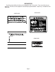
USER NOTICES Carefully read and follow all notices on the equipment and in this manual. They were written for your protection. All notices on the equipment should be kept in good condition. Replace any unreadable or damaged labels. #00658.0000 #00656.0000 #00882.
ELECTRICAL REQUIREMENTS CAUTION - The brewer must be disconnected from the power source until specified in Initial Set-Up. The brewer has an attached cordset and requires 2-wire, grounded service rated 120 volts ac, 15 amp, single phase, 60 Hz. PLUMBING REQUIREMENTS This brewer must be connected to a cold water system with operating pressure between 20(138) and 90 psi(620 kPa) from a 1/2” or larger supply line. A shut-off valve should be installed in the line before the brewer.
INITIAL SET-UP CAUTION - The brewer must be unplugged throughout the Initial Set-up, except when specified in the instructions. 1. 2. 3. 4. 5. Remove the top lid from the brewer. Rotate the control thermostat knob fully counterclockwise to the “OFF” position and replace the top lid. Insert an empty funnel into the funnel rails. Place a decanter containing a small amount of water on the left warmer. Plug in the brewer and place the On/Left switch in the upper position.
ADJUSTING BREW VOLUMES(cont) 2. Setting batch sizes. To set a batch volume, first check that the SET/LOCK switch is in the “SET” position on the circuit board. Press and hold the START or BREW switch until three distinct clicks are heard, and then release the switch. (Failure to release the switch within two seconds after the third click causes the volume setting to be aborted and previous volume setting will remain in memory). View the level of the liquid being dispensed.
TROUBLESHOOTING A troubleshooting guide is provided to suggest probable causes and remedies for the most likely problems encountered. If the problem remains after exhausting the troubleshooting steps, contact the Bunn-O-Matic Technical Services Department. • Inspection, testing, and repair of electrical equipment should be performed only by qualified service personnel. • All electronic components have 120 volt ac and low voltage dc potential on their terminals.
TROUBLESHOOTING (cont.) PROBLEM PROBABLE CAUSE REMEDY Equipment will not operate 1. No power or incorrect voltage (A) Plug in brewer. (B) Check wall outlet for 120V ac (C) Check circuit breaker/fuse. Brew cycle will not start 1. No water Check plumbing and shut-off valves. 2. Water strainer/Flow Control (A) Direction of flow arrow must be pointing towards brewer. (B) Remove the strainer/Flow control and check for obstructions. Clear or replace. 3.
TROUBLESHOOTING (cont.) PROBLEM PROBABLE CAUSE REMEDY Automatic refill will not operate after drawing hot water.(cont.) 2. Liquid level control system Refer to Service - Liquid Level Control system for testing procedures. See page 20. 3. Relay Refer to Service - Relay for testing procedures. See Page 23. 4. Solenoid valve Refer to Service - Solenoid valve for testing procedures. See page 25. Water flows into tank continuously (On/left switch “OFF”) 1.
TROUBLESHOOTING (cont.) PROBLEM PROBABLE CAUSE REMEDY Decanter warmer is not hot 1. Warmer switches (A) The decanter warmer switch must be in the upper position for the warmer to operate. (B) Refer to Service - On/Left or Right switch for testing procedures. See page 22 or 24. 2. Decanter warmers Refer to Service - Decanter Warmer for testing procedures. See page 18. 1. Control thermostat Refer to Service - Control Thermostat for testing procedures. See page 17. 2.
TROUBLESHOOTING (cont.) PROBLEM PROBABLE CAUSE REMEDY Inconsistent beverage level in decanter (cont.) 3. Syphon System Water should flow freely from the sprayhead for approximately twenty seconds after the brew solenoid has shut off and then stop flowing abruptly. The brewer must be level from side-to-side to syphon properly. Consistently high or low beverage level in decanter. 1. Brew timer adjustment Adjust the brew timer as required to achieve the recommended 64 oz. for each brew cycle.
TROUBLESHOOTING (cont.) PROBLEM PROBABLE CAUSE REMEDY Weak beverage (cont.) 4. Funnel loading The BUNN® paper filter should be centered in the funnel and the bed of ground coffee leveled by gentle shaking. 5. Water temperature Empty a decanter and place it on the left warmer. Insert an empty funnel into the funnel rails. Place the On/left switch in the upper position. Press the Start switch and check the water temperature immediately below the sprayhead with a thermometer.
SERVICE This section provides procedures for testing and replacing various major components used in this brewer should service become necessary. Refer to Troubleshooting for assistance in determining the cause of any problem.
SERVICE (cont.) BREW TIMER (early models) 6. Disconnect the in-line connectors on the black and white wires from the timer to the wiring harness. 7. With a voltmeter, check the voltage across the black and white wires when the On/Left switch is in the upper position and the Start switch is pressed to the lower position and released. Connect the brewer to the power source. The indication must be 120 volts ac for approximately 20 seconds and then return to its previous indication. 8.
SERVICE (cont.) BREW TIMER (cont.)(late models) 5. With a voltmeter, check the voltage across terminals TL1 and TL4 when the “ON/OFF” switch is in theh “ON” position. Connect the brewer to the power source. The indication must be 0 volts. If voltage is as described, proceed to #6. If voltage is not as described, disconnect the brewer from the power source and replace the timer. 6. With a voltmeter, check the voltage across terminals TL1 and TL4 when the “ON/OFF” switch is in the “ON” position.
To increase a brew volume, place the ON/OFF switch in the “ON” position, press and hold the START switch until three clicks are heard. Release the switch and press it again one or more times. (Failure to release the switch within two seconds after the third click causes the volume setting to be aborted and previous volume setting will remain in memory) Each time the switch is pressed, two seconds are added to the brew time period.
SERVICE (cont.) 6. Disconnect the brewer from the power source. If voltage is present as described, reconnect the blue wire, the control thermostat is operating properly. If voltage is not present as described, replace the control thermostat. Location: The control thermostat is located on the rear of the hood to the right of the tank. Test Procedure: 1. Disconnect the brewer from the power source and remove the black wire from the control thermostat. 2.
SERVICE (cont.
SERVICE (cont.) LIMIT THERMOSTAT Location: The limit thermostat is located on the tank lid between the tank heater terminals. Test Procedure: 1. Disconnect the brewer from the power source and remove the blue wire from the limit thermostat. 2. With a voltmeter, check the voltage across the blue wire removed from the limit thermostat and the white wire on the tank heater terminal when the control thermostat is turned “ON” (fully clockwise). Connect the brewer to the power source.
SERVICE (cont.) LIQUID LEVEL CONTROL SYSTEM 6. FF IH O BUNN 7. 8. 9. 658 PN: from any metal surface of the brewer. With a voltmeter, check the voltage across terminals 1 & 3 when the On/Left switch is in the upper position. Connect the brewer to the power source. The indication must be 120 volts ac after a delay of approximately 5 seconds. Touch the end of the jumper wire to the brewer housing. The indication must be zero. Move the jumper wire away from the brewer housing.
SERVICE (cont.) LIQUID LEVEL CONTROL SYSTEM (cont.) Removal and Replacement: 1. Remove all wires from the liquid level control board terminals. 2. Remove the two #8-32 slotted-head screws holding the circuit board to the brewer hood. 3. Install the new circuit board to the hood, making sure that the two lock-washers are in place below the board and above the spacers. 4. Refer to FIG. 13 when reconnecting the wires. WHI/BRN to Relay (Term. #2) WHI/RED to Start Switch WHI/RED to Relay(Term.
SERVICE (cont.) ON/LEFT SWITCH If continuity is not present as described, replace the switch. Removal and Replacement: 1. Remove all wires from the switch terminals. 2. Compress the clips inside the hood and gently push the switch through the opening. 3. Push the new switch into the opening and spread the clips to hold the switch captive in the panel. 4. Refer to FIG. 15 when reconnecting the wires.
SERVICE (cont.) RELAY 7. Check for continuity across terminals 2 & 7 when the On/Left switch is in the upper position only until the Start switch is pressed to the lower position and released. Connect the brewer to the power source. Continuity must return across these terminals after the approximate setting on the brew timer dial. 8. Disconnect the brewer from the power source. 9.
SERVICE (cont.) RIGHT SWITCH WHI Tank Keep Warm Heater Lead WHI to On/Left Switch WHI to Solenoid Location: The Right switch is located in the front of the hood, above and to the right of the brew funnel. Test Procedure: 1. Disconnect the brewer from the power source and remove the wires from all three terminals of the Right switch. 2. With a voltmeter, check the voltage across the black and white wires. Connect the brewer to the power source. The indication must be 120 volts ac. 3.
SERVICE (cont.
START SWITCH Page 26
SERVICE (cont.) TANK HEATER NOTE - If the tank heater remains unable to heat, remove and inspect the heater for cracks in the sheath. 658 PN: P1983 FIG. 24 TANK HEATER Location: The tank heater is located on the tank lid. Test Procedure: 1. Disconnect the brewer from the power source and remove both wires from the tank heater. 2. With a voltmeter, check the voltage across the black and white wires removed from the tank heater when the control thermostat is turned “ON” (fully clockwise).
Page 28 10179 091599