
Corporation Grind and Brew Coffeemaker OPERATING & SERVICE MANUAL VLPF

Page 13
SERVICE
This section provides procedures for testing and
replacing various major components used in this
brewer should service become necessary. Refer to
Troubleshooting
for assistance in determining the
cause of any problem.
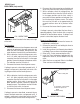
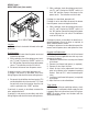
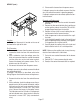
COMPONENT ACCESS
WARNING - Unplug the brewer before the removal of
any panel or the replacement of any component
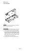
The On/Left switch, Start switch, Right switch,
solenoid valve, brew timer, liquid level control com-
ponents, relay, control thermostat, limit thermostat,
and tank heater are located in the hood. Access is
gained by removing the top lid, attached with two #4-
40 slotted-head screws.
WARNING - Inspection, testing, and repair of electri-
cal equipment should be performed only by qualified
service personnel. The brewer should be unplugged
when servicing, except when electrical tests are re-
quired and the test procedure specifically states to
plug in the brewer.
CONTENTS
Brew Timer .................................................... 14
Control Thermostat........................................ 17
Decanter Warmer(s) ...................................... 18
Limit Thermostat ........................................... 19
Liquid Level Control System .......................... 20
On/Left Warmer Switch ................................. 22
Relay.............................................................. 23
Right Warmer Switch .................................... 24
Solenoid Valve ............................................... 25
Start Switch ................................................... 26
Tank Heater .................................................... 27
Wiring Diagram ............................................. 28