
- BUNN VPR TC, VPR APS OPERATING & SERVICE MANUAL


Page 9
Location:
The control thermostat is located inside the hood
on the left end of the mounting bracket.
Test Procedures:
1. Disconnect the brewer from the power source.
2. Locate the black wire on the control thermo-
stat.
3. Check voltage across the black wire on the control
thermostat and the white wire on the tank heater
with a voltmeter. Plug-in the brewer to the power
source. The indication must be 120 volts ac.
4. Disconnect the brewer from the power source.
If voltage is present as described, proceed to #5.
If voltage is not present as described, refer to the wiring
diagram and check the brewer wiring harness.
5. Locate the blue/black wire on the control ther-
mostat.
6. Gently remove the capillary bulb and grommet
from the tank.
7. Check voltage across the blue/black wire of the
control thermostat and the white wire on the
tank heater with a voltmeter when the control
thermostat is turned "ON" (fully counterclockwise
for thermostat with tee handle control or fully
clockwise for thermostats with control knob).
Plug-in the brewer to the power source. The
indication must be 120 volts ac.
Voltage must not be present across these terminals
when the thermostat is turned "OFF" (fully counter-
clockwise).
8. Disconnect the brewer from the power source.
If voltage is present as described, reinstall the capillary
tube into the tank to the line 4.5" above the bulb, the
control thermostat is operating properly.
If voltage is not present as described, replace the
thermostat.
SERVICE (cont.)
Removal and Replacement:
1. Remove wires from control thermostat leads or
terminals.
2. Remove the thermostat capillary bulb by fi rmly
pulling-up on the capillary at the tank lid. This
will disengage the grommet from the tank lid.
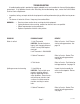
P1252
FIG.4 CONTROL THERMOSTAT TERMINALS
BLK to Terminal Block
BLU/BLK to
Limit Thermostat
or Thermal Cut-Off
3. Remove two #8-32 screws securing the control
thermostat to the mounting bracket inside the
hood.
4. Slide the grommet to the line 4.5" above the bulb
on the new capillary tube.
5. Insert the capillary bulb through the hole in the
tank lid and press the grommet fi rmly and evenly
so that the groove in the grommet fi ts into the
tank lid.
6. Carefully bend the capillary tube so that the tube
and bulb inside the tank are in the vertical posi-
tion.
NOTE - The capillary tube must be clear of any electri-
cal termination and not kinked.
7. Using two #8-32 screws secure the control
thermostat to the mounting bracket inside the
hood.
8. Refer to Fig. 4 when reconnecting the wires.
9. Adjust the control thermostat as required
39064 042806