INSTALLATION INSTRUCTIONS W W W. B U R C A M . C O M 2190 Boul. Dagenais West LAVAL (QUÉBEC) CANADA H7L 5X9 TEL: 514.337.4415 FAX: 514.337.4029 SERIES info@burcam.com 101 / 105 Your pump has been carefully packaged at the factory to prevent damage during shipping. However, occasional damage may occur due to rough handling. Carefully inspect your pump for damages that could cause failures. Report any damage to your carrier or your point of purchase.
SAFETY INSTRUCTIONS: This fine pump that you have just purchased is designed from the latest in material and workmanship. Before installation and operation, we recommend the following procedures: A CHECK WITH YOUR LOCAL ELECTRICAL AND PLUMBING CODES TO ENSURE YOU COMPLY WITH THE REGULATIONS. THESE CODES HAVE BEEN DESIGNED WITH YOUR SAFETY IN MIND. BE SURE YOU COMPLY WITH THEM.
Material required for drilled well application Deep well pump Desired length of polyethylene 1” pipe, 100 PSI, CSA or UL approved to link up from pumping level to pump. 1 Poly rope Well seal (150156). Pitless adaptor (150155). 1” male brass adaptors (750871). 1” stainless steel clamps (750885). Electrical tape. Teflon tape. Pressure relief valve 1/2” NPT. Torque arrestor (150158) Tank installation Desired length of 1” braided hose (750919) to link up from pump to tank.
150143 (4 tubes) / 150152 (3 tubes) HEAT SHRINK SPLICING KIT SHRINKING TECHNIQUE Shrinking can be accomplished through the use of a thermo gun or flame torch with a utility head or other broad flame. Begin at one end of tubing. Keep tubing out of direct contact with flame. Keep flame moving back and forth. Progress toward other end as tubing shkinks and wrinkles disappear. Keep the flame moving. STEP 1 Strip approx. 1/4” (6mm) of wire insulation from both end of wires to connect.
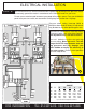
ELECTRICAL INSTALLATION STEP 9 We recommend that a licensed electrician be employed to do wiring to the pressure switch. Permanently ground the motor in accordance to the electrical codes for your area. Do not use an extension cord to connect your pump to the power source. From your distribution panel to the pressure switch, we recommend a wire gauge not smaller than 14 gauge. 4 WIRE 3 WIRE TO ELECTRICAL PANEL Pressure switch setting (start/stop 20/40 or 30/50) has been made in factory.
STEP BY STEP INSTALLATION INSTRUCTION FOR YOUR NEW DEEP WELL PUMP STEP 1 Lay the pump on the ground a foot or two from the well head, with the discharge end pointing away from the well. If you have purchased a Sub-Pac, the wire and (splice kit) will be attached to the motor pigtail. STEP 2 Your submersible pump is equipped with a check valve installed in the discharge opening of pump.
STEP 7 Roll out the submersible pump cable, on the ground, along side of your 1” plastic Poly pipe, and at 5 foot intervals using your electrical tape - tape the cable to the pipe. This will prevent the cable from hitting the well casing when lowering pump into the well. STEP 8 Securely attached your 1/4 poly safety rope to the lug provided on the discharge end of your submersible pump. This rope should be long enough to reach the pump setting in your well, when lowered.
AIR PRESSURE TANK INSTALLATION STEP 10 for captive air tanks When using a separate tank from your pump, we recommend to install a captive air tank as shown in our typical installation diagram, that is air injected into the tank at the factory. This air, which is in addition to atmospheric pressure, increase the ability of the tank to deliver more water between on/off cycles, thus increasing the efficiency of your water system.
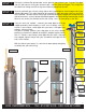
AIR PRESSURE TANK INSTALLATION STEP 1 “Free-Standing” type tanks have to be installed offset from your pump, and in “the line” coming from your pump’s discharge connection (either a jet or submersible pump). Turn your tank on its side and install a galvanized 90º elbow (1” or 1 1/4” as per needed) to the inlet-outlet connection, using an ample supply of teflon tape on the treads. STEP 2 Determine the position or location in which you wish to leave your tank permanently.
REPLACEMENT PUMP MODELS ALL STAINLESS STEEL 5 GPM 1-11/4” DISCHARGE MODELS HP V Wire Stage 101124 1/2 115 2 13 101125 1/2 115 3 13 101126 1/2 230 2 13 101074 1/2 230 3 13 101134 3/4 230 2 18 101135 3/4 230 3 18 101059 3/4 230 3 18 101144 1.0 230 2 22 101145 1.0 230 3 22 101156 1.5 230 2 26 101154 1.
REPAIR PARTS ALL STAINLESS STEEL SERIE Pump head Models 111127 111135 111145 111154 111128 111136 111146 111155 STAINLESS STEEL & NORYL SERIE Pump head Models 115307ST 115309ST 115313ST 115316ST Description 13 stages 18 stages 22 stages 26 stages 9 stages 12 stages 15 stages 21 stages Pump motor Models Description 125127 1/2 HP 115V 2 wire 125227 1/2 HP 115V 3 wire 125128 1/2 HP 230V 2 wire 125228 1/2 HP 230V 3 wire 125130 3/4 HP 230V 2 wire 125229 3/4 HP 230V 3 wire 125132 1.0 HP 230V 2 wire 125235 1.
TROUBLE SHOOTING GUIDE CHECKLIST NEVER MAKE ADJUSTMENTS TO ANY ELECTRICAL APPLIANCE OR PRODUCT WITH THE POWER CONNECTED. DON’T JUST UNSCREW THE FUSE OR TRIP THE BREAKER, REMOVE THE POWER FROM THE RECEPTACLE. TROUBLE PROBABLE CAUSE Motor does not run.