
User guide


1150 - 19
INSTALLATION, COMMISSIONING AND MAINTENANCE
Installation
• The choice of cable - the installation and the electrical connection must conform to the requirements of
VDE 0100 “Regulations on the Installation of Power Circuits with Nominal Voltages below 1000 V” or the
appropriate local regulations.
• The electrical connection may only be carried out by properly qualified personnel.
• The instrument must be disconnected/isolated electrically incase of accidental contact with live parts.
• A current-limiting resistor interrupts the supply circuit in the event of a short-circuit. However, the load
must be fused for the maximum relay current to prevent the contacts of the output relay from becoming
welded in the event of a short-circuit.
• Electromagnetic compatibility conforms to the standards and regulations cited in the technical data
(see Chapter Technical data).
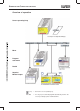
• Run input, output and supply cables separately and not parallel to one another.
• All input and output signal cables must be shielded twisted pairs to prevent crosstalk, electrical noise
and interferences.
• The shield of all transmission lines must be connected on the instrument side to potential earth.
• The PE terminal on the instrument must be connected to earth ground. This cable must have at least
the same conductor cross-section as used for the supply cables. Grounding and earthing leads must be
wired in a star configuration to a common earth point that is connected to the protective earth of the
electrical supply. Do not loop earth or ground connections, i.e. do not run them from one instrument to
another.
• Do not connect any additional loads to the supply terminals of the instrument.
• The instrument is not suitable for use in areas with an explosion hazard (Ex areas).
• In addition to faulty installation, incorrect programming/configuration of the controller (setpoint, data of
the parameter and configuration levels, internal alterations) can also interfere with the correct operation
of dependent processes, or even cause damage. Safety devices should always be provided that are
independent of the controller (such as overpressure valves or temperature monitors/limiters) and only
capable of adjustment by authorized personnel.
• Since adaptation (self-optimization) cannot be expected to handle all possible control loops, an unstable
process parameterization is theoretically possible. The stability of the actual value derived from the self-
tune should therefore be checked.
• The measurement inputs of the controller must not exceed a maximum potential of 30 V AC or 50 V DC
against PE.
ATTENTION!
Please observe the relevant safety regulations and electrical installation codes for your
area.