
Manual


Table Of Contents
22
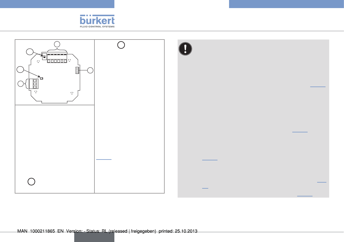
INstallation
123456
4...20V+V-PEPls+Pls-
C
NO
NC
B
A
2
1
3
Selector
A
: Sink/source
selector of the 4-20 mA
output
Terminal block 3
Terminal 1: 4-20 mA output
Terminal 2: V+ (positive
voltage)
Terminal 3: V- (power supply
ground)
Terminal 4: PE, shield of
the power supply cable;
Earth cable coming from the
housing and, second cable
on a version with flow sensor
holder in stainless steel (see
Fig. 15)
Terminal 5: Pls+, positive
frequency output
Terminal 6: Pls-, negative
frequency output
Connector 1: connection of the
flat cable coming from the flow
sensor (to energize the flow
sensor)
Terminal block 2: wiring the
relay output
C: common point
NO: normally open
NC: normally closed
LED
B
: status LED of the relay
(LED ON = contact closed)
Fig. 14: Terminal assignment
Make sure the installation is equipotential (power supply
- 8041):
→ Connect together the various earth spots in the instal-
lation to eliminate the potential differences that may occur
between two earthes.
→ In the housing, connect the power supply cable shield to
terminal no. 4 of the electronic board connector (Fig. 15
).
On a version with stainless steel flow sensor, a second
cable is coming from the sensor.
→ Connect the negative power supply terminal to the earth
to suppress the effects of common mode currents. If
this connection cannot be made directly, a 100 nF/50 V
capacitor can be connectec between the negative power
supply terminal and the earth (marked 1, Fig. 16).
• If the pipes are made of metal:
→ connect to the same earth the different metallic instru-
ments (valve, pump...) located near the device (marks 2,
Fig. 16).
• If the pipes are made of plastic:
→ insert the metal parts (not provided) in the plastic pipes,
upstream and downstream of the device (marked 2, Fig.
16).
→ connect the metal parts to the same earth (Fig. 16).
English
Type 8041