
User guide

37
Operating and functions
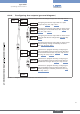
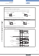
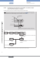
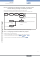
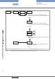
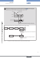
8.6.5. Configuring the outputs (general diagram)
OUtPUt AO1
0......9
DO1 PULsE
hYstEREs.
wiNDOw
DiRECtiO.
wARNiNG
DO2
DO3
REtURN
hYstEREs.
wiNDOw
Parameterizing the 4-20 mA analogue output, AO1. See chap. “8.6.6”.
Configuring the transistor output DO1 as a pulse
output. See “Fig. 34”, chap. “8.6.7”.
Configuring the transistor output DO1 to switch a load
depending on two threshold values. See “Fig. 36” and
“Fig. 35”, chap. “8.6.7”.
If the device is equipped with relays, configuring the
relay output DO2 or DO3 to switch a load depending
on two threshold values. See “Fig. 36”, chap. “8.6.7”
and “Fig. 40” chap. “8.6.11”.
Configuring the transistor output DO1 to switch a load
when the fluid direction changes. See “Fig. 38” chap.
“8.6.7”.
Configuring the transistor output DO1 to switch a load
when a warning message is emitted by the device.
See “Fig. 39” chap. “8.6.7”.
DiRECtiO.
wARNiNG
If the device is equipped with relays, configuring the
relay output DO2 or DO3 to switch a load when the
fluid direction changes. See “Fig. 41” chap. “8.6.11”.
If the device is equipped with relays, configuring the
relay output DO2 or DO3 to switch a load when a
warning message is emitted by the device. See “Fig.
42” chap. “8.6.11”.
0......9
0......9
Fig. 32: Diagram of the "OUTPUT" parameter of the Parameters menu
English
Type 8045