INSTALLATION, OPERATING AND SERVICE INSTRUCTIONS FOR ESC™ ENHANCED SEALED COMBUSTION Gas - Fired Boiler 9700609 For service or repairs to boiler, call your heating contractor. When seeking information on boiler, provide Boiler Model Number and Serial Number as shown on Rating Label. Boiler Model Number ESC_C Heating Contractor Boiler Serial Number Installation Date Phone Number Address 103788-03 - 9/13 Price - $5.
WARNINGS for the HOMEOWNER FOLLOW ALL INSTRUCTIONS and warnings printed in this manual and posted on the boiler. INSPECT THE BOILER ANNUALLY. To keep your boiler safe and efficient, have a service technician follow the Service checklist near the end of this manual. IF YOU ARE NOT QUALIFIED to install or service boilers, do not install or service this one. THE BOILER MAY LEAK WATER at the end of its useful life. Be sure to protect walls, carpets, and valuables from water that could leak from the boiler.
WARNINGS for the INSTALLER READ THIS ENTIRE MANUAL before attempting installation, start-up, or service. Improper installation, adjustment, alteration, service, or maintenance may cause serious property damage, personal injury, or death. DO NOT DISCONNECT PIPE FITTINGS on the boiler or in the heating system without first verifying that the system is cool and free of pressure and that your clothing will protect you from a release of hot water or steam.
Special Installation Requirements for Massachusetts A. For all side wall horizontally vented gas fueled equipment installed in every dwelling, building or structure used in whole or in part for residential purposes and where the side wall exhaust vent termination is less than seven (7) feet above grade, the following requirements shall be satisfied: 1.
Congratulations on your purchase of a new ESC™ boiler—designed and constructed to provide you with years of reliable service. • Cast iron heat exchanger – for reliability and durability, nothing beats a cast iron heat exchanger. • IQ Control™ System – the most advanced and easiest to use control available. • System-friendly – built-in protection from condensation and thermal shock. *IQ Control System Overview ESC Boiler uses a microprocessor based control system called the "IQ Control System".
SPECIFICATIONS Ratings ESC Series Boiler Model Heating Capacity (MBH) Input (MBH) Net AHRI Rating, Water (MBH) (1) AFUE (%) ESC3C 60.8 52 45 85.5 ESC4C 91.2 78 68 85.4 ESC5C 121.6 104 90 85.3 ESC6C 152.0 130 113 85.2 ESC7C 182.4 156 136 85.0 ESC8C 212.8 180 157 84.5 ESC9C 243.2 206 179 84.0 (1) Net AHRI Water Ratings shown based on piping and pickup allowance of 1.15.
SPECIFICATIONS (continued) Figure S-1: Minimum Clearances to Combustibles 7
Boiler Quick-Start Installation: 1. Unpack the crate.............................................................................................. 9 2. Position the boiler............................................................................................. 9 3. Provide combustion air................................................................................... 10 4. Connect venting.............................................................................................. 10 5.
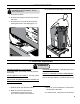
1. Unpack the Crate 4. Tip the boiler and shimmy it off the skid. THE BOILER IS TOP-HEAVY. Do not allow it to tip over. 1. Remove the sleeve. 2. Remove the contents from the skid, except the boiler. 3. Remove the four (4) hex-drive lag screws holding the boiler to the skid (Figure 1-a). 1-a 1-b 2. Position the Boiler WARNINGS OBSERVE MINIMUM CLEARANCES to combustible walls and ceilings to avoid potential fire hazard. DO NOT INSTALL ON CARPET. This may cause a fire.
3. Provide Combustion Air INSUFFICIENT COMBUSTION AIR SUPPLY may result in the production and release of deadly carbon monoxide (CO) into the home. Provide combustion and ventilation air in accordance with the section "Air for Combustion and Ventilation," of the National Fuel Gas Code, ANSI Z223.1/NFPA 54, or applicable provisions of the local building codes. Like all fuel-burning appliances, boilers need air to operate reliably and safely. 1.
4. Connect Venting (continued) (3) Install vent piping. (4) When configuring the ESC for Power Vent (indoor combustion air) install a 45° vent elbow, pointing downward. (5) Install vent terminal and seal around all exterior openings. (6) The final installation should appear as in Figure 4-c. 4. For vertical venting, follow instructions in Appendix B2 Direct Venting, Special Instructions for Stainless Steel Venting Vertical Installations, Specifically, (4) Install roof flashing and roof supports.
5. Connect Gas Piping Size gas piping according to Appendix C – Gas Piping 3. Pipe from the street elbow through the left jacket panel, and complete drip leg as shown (Figure 5-a). SHUT OFF GAS SUPPLY before servicing the boiler. ALL GAS PIPING MUST BE GAS TIGHT. Use gas rated thread compound on all threaded joints to avoid leaks, which may result in fire or explosion. SIZE GAS PIPING, regulators, valves, and meters so as to provide an adequate gas flow and pressure to the boiler during operation.
6. Connect Boiler Water Piping (continued) 6. Connect the system supply to the open end 9. See Figure 6b for suggested near boiler of the manifold "S" using a 1¼” male NPT fitting. piping of IQ Options. 10. Maintain minimum 1/2" clearance between 7. Screw an installer-supplied 1¼” pipe or water piping and combustible construction. nipple into the water return tapping “R”. 8. Screw the supplied drain valve into tapping “D”.
7. Connect Electrical Wiring DISCONNECT ELECTRICAL POWER to the boiler and heating system before servicing. Positively assure that no voltage is present. Lock electrical boxes to prevent someone from inadvertently restoring power before the heating system is safe to operate. NEVER DEFEAT OR JUMP OUT safety devices. PROTECT EACH BOILER circuit with a properly sized over-current protection device.
8. Program the Controls 1. Press and release the “I” key on the IQ Using Intelligent Hydronic Control Display control to change from one parameter to the next. Each setting will alternately flash between the relevant display code and its corresponding value. The Intelligent Hydronic Control is located inside the boiler front door, just above the IQ Option Panel (Figure 8-a).
8. Program the Controls (continued) Please note that in operating mode to hold the display on the value the user can press and hold either the Up ñ or Down ò keys and the value will be continuously shown. This may be helpful in watching a value “live”. Changing the Adjustable Parameters To adjust the Parameters such as High Limit Setpoint and High Limit Differential: 1. Access the adjustment mode by pressing and holding the Up , Down , and “I” keys simultaneously for three (3) seconds.
8. Program the Controls (continued) Table 8a: Circulator Pre-purge Time example, (PP_ = 2 minutes) Call for Heat Source TT = on TT = on DHW = on DHW = on DHW = on DHW = on DHW Boiler Terminal Temperature Selection tt2 tt2 dh dh <140 >140 <140 >140 <140 >140 7. Domestic Hot Water (DHW) Terminal Function () The control allows configuration of the DHW Circulator output functionality to help the ESC integrate into each installation more effectively.
8. Program the Controls (continued) b. When is set equal to Second Heating Zone () When there is no IWH the “DHW Circulator” output may be configured to control a second heating zone. This is particularly helpful when the home uses only two heating zones. The control replaces the need for a two circulator zone panel. When DHW Terminal Function () is set to “" the control’s two circulator outputs are used to control two independent heating zones. Refer to Table 8c.
10. Perform Startup Checks and Adjustments FAILURE TO PERFORM THESE CHECKS of the boiler's combustion and safety systems may result in serious property damage, injury, or death. IF YOU SMELL GAS, STOP and repair the leak. Lighting the boiler when gas is leaking may cause explosion or fire. Follow the checklist below: 1. Verify that the venting, water piping, gas piping, and electrical systems are properly installed and checked. 2. Apply power to the boiler. 10-b 3.
10.
Annual Maintenance Checklist Important Product Safety Information Refractory Ceramic Fiber Product Warning: The Repair Parts list designates parts that contain refractory ceramic fibers (RCF). RCF has been classified as a possible human carcinogen. When exposed to temperatures about 1805°F, such as during direct flame contact, RCF changes into crystalline silica, a known carcinogen.
Annual Maintenance Checklist (continued) WARNINGS LABEL ALL WIRES prior to disconnection when servicing controls. Wiring errors can cause improper and dangerous operation FAILURE TO MAINTAIN THE BOILER in proper working condition may lead to fire, explosion, personal injury or death, and extensive property damage. TURN OFF ALL GAS AND ELECTRIC power supplies to the boiler before servicing.
Troubleshooting wiring diagram in Figures IW-1 and IW-2. Ensure that incoming 120 Vac power polarity is correct and that the boiler is properly grounded. Further, ensure that the control power supply is 24 VAC (minimum 18 VAC to maximum 30 VAC) and polarity is correct. Before troubleshooting The following pages contain trouble shooting tables for use in diagnosing control problems. When using these tables the following should be kept in mind: 1.
Troubleshooting (continued) Use Control Display (error) Number To Direct TroubleShooting Efforts If the control detects an error it will flash “” (error) followed by a number. Use this number to identify the boiler problem and corrective action in the table below.
Troubleshooting (continued) Use STA (status) Number To guide TroubleShooting The control will flash “” followed by a number. Use this number to identify the boiler problem in the table below: 1. Boiler and Circulator Off Display / Status Recommended Corrective Action The boiler has not detected a call for heat (tt = off and dh = off).
Troubleshooting (continued) 5. Circulator is On, Blower is On but Boiler Fails to Start Display / Status Retry / Recycle Delay StA 11 Pressure Switch Failed to Open STA 12 Pressure Switch Failed to Close Soft Lockout Hard Lockout Flame Out of Sequence 26 Description The Boiler is in “Retry Delay”: - The burner failed to light (no flame signal). After a 5 minute delay, control will attempt to light the burner again. There is no limit to the number of retries.
Troubleshooting (continued) Display / Status Recommended Corrective Action 1. No Spark a. Can you hear sparking while is displayed? - If there is no spark noise replace the control. b. If you can hear spark noise check the following: - Loose connection in ignition cable or ground wire - Continuity of ignition cable - Break in ignition cable insulation - Loose ground connection - Break in pilot ceramic insulator - Incorrect pilot spark gap StA 10 Retry / Recycle Delay StA 13 Soft Lockout 2.
Troubleshooting (continued) If Control Shows Status Code “STA 15": The control is “Waiting for Limit to Close” and the display on the IQ Option Panel should be the first place to check.
Repair Parts All ESC™ Repair Parts may be obtained through your local U.S. Boiler Company Wholesale distributor. Should you require assistance in locating a U.S. Boiler Company Distributor in your area, or have questions regarding the availability of U.S. Boiler Company products or repair parts, please contact U.S. Boiler Company Customer Service at (717) 481-8400 or Fax (717) 481-8408. Key No.
Repair Parts (continued) Key No.
Repair Parts (continued) Key No.
Repair Parts (continued) Key No. 4A 4B 4C 4D 4E Description Gas Valve (Natural Gas), Honeywell VR8204P1171 Gas Valve (Natural Gas), Honeywell VR8304P4496 Gas Valve (LP Gas), Honeywell VR8204C3015 Gas Valve (LP Gas), Honeywell VR8304P4280 ½" Gas Manifold ¾" Gas Manifold Burner Orifices - Natural Gas #49 Burner Orifices - LP Gas #56 Pilot Burner Pilot Assembly - Natural Gas Pilot Assembly - LP Gas 4F Main Burner 4G 4H 4J 4K 4L Pilot Tubing Gas Valve Hose Barb Fitting Plastic Hole T 24" Lg.
Repair Parts (continued) Key No.
Repair Parts (continued) Key No.
Repair Parts (continued) Key No.
Repair Parts (continued) Key No.
Internal Wiring Figure IW-1: Wiring Diagram 37
Internal Wiring (continued) 38 Figure IW-2: Wiring Diagram
Internal Wiring (continued) Figure IW-3: Multiple Zone System with Zone Circulators Figure IW-4: Multiple Zone System with Zone Valves 39
Internal Wiring (continued) Figure IW-5: Multiple Zone System with Zone Circulator Panel POWER SUPPLY 120/60/1 DHW AQUASTAT (L4006, L4080) (SUPPLIED BY OTHERS) L2 L1 THERMOSTAT THERMOSTAT THERMOSTAT 24V TRANSFORMER MODE ZONE 4 PRIORITY DOMESTIC HOT WATER PRIORITY IS SELECTED USING ZONE PANEL SWITCH NORMAL RESET OFF POWER IN T T ZONE 1 T T ZONE 2 FUSE (3 AMP MAX.
APPENDIX A – Combustion Air PROVIDE ENOUGH AIR to ventilate the boiler room, dilute the flue gases, and sustain combustion. Ignition failure, overheating, fire, carbon monoxide, and spillage of flue gases may result from poor air supply. If the boiler is a Direct Vent boiler and exchanges all combustion air and combustion products directly with the outdoors, there are no special requirements for providing combustion, ventilation, and dilution air.
APPENDIX B – Venting VENT THIS BOILER according to the instructions. Failure to do so may cause products of combustion to enter the building resulting in severe property damage, personal injury or death. i Install this boiler according to this manual and the National Fuel Gas Code, ANSI Z223.1/NFPA 54, or applicable provisions of the local building codes. Contact local building or fire officials about restrictions and installation inspection in your area.
APPENDIX B2 – Direct Venting GENERAL WARNINGS for DIRECT VENT SYSTEMS Draft hoodS, VENT DAMPERS and other obstructions or openings in the vent system are prohibited. IF USING A CHIMNEY AS A CHASE for the vent, do not vent any other appliance into the space between the chimney wall and the vent. DO NOT REDUCE THE DIAMETER of the vent pipe. ELIMINATE LOW SPOTS in the vent where flue gas condensate may pool. MOISTURE AND ICE may collect around and below the vent terminal. Keep the area in good repair.
APPENDIX B2 – Direct Venting (continued) Figure B-2: Approved Terminal Locations However, boiler may be installed with vertical venting and sidewall combustion air inlet or visa versa, if installation conditions do not allow alternate arrangement. 10. If the vent passes through interior spaces in floors above the boiler room, enclose the vent with material having a fire resistance rating at least equal to the rating of the adjoining floor or ceiling.
APPENDIX B2 – Direct Venting (continued) Special Instructions for Stainless Steel Direct Vent USE STAINLESS STEEL VENTING only with boilers approved for use with stainless steel venting as noted in the Specifications Section of this manual. AL 29-4C® stainless steel vent systems resist the corrosive effects of high temperature acidic flue gas condensate and are leak-tight. Alternate stainless steel venting systems require special adaptors to connect to the parts supplied with the boiler.
APPENDIX B2 – Direct Venting (continued) Special Instructions for Stainless Steel Direct Vent (continued) Vent/Combustion Air, Equivalent Length Work Sheet This sheet is supplied to assist in vent/combustion air, equivalent length calculating Combustion Air (PVC shown) 90° elbow(s) PVC Quantity = 90° elbow(s) x 5’ = equiv. ft. a. 45° elbow(s) PVC Quantity = Quantity = x 5’ = equiv. ft. a. x 5’ = equiv. ft. b x1= equiv. ft. c. x 2' = equiv. ft. d. x 7' = equiv. ft. e. 45° elbow(s) x 2.
APPENDIX B2 – Direct Venting (continued) Special Instructions for Stainless Steel Direct Vent (continued) (1) Insert the wall thimble from the outside of the wall, and secure the outside flange to the wall using nails or screws. (2) Seal any exterior openings in the wall thimble, or between the thimble and the wall, using a weatherproof sealant. (3) Install the inside thimble flange and secure the flange to the inside wall using screws or nails. 3. Maintain 12" separation between vent and intake terminals.
APPENDIX B2 – Direct Venting (continued) Special Instructions for Stainless Steel Direct Vent (continued) Figure B-6: Typical Vertical Stainless Steel Venting 6. Install the intake air terminal supplied with 3. Apply Dow Corning Silastic 732 RTV Sealant 7. Install the vent terminal supplied with the 4. Install the vent terminal per the boiler- the boiler onto the outdoor end of the air intake pipe per the instructions in Connect Venting in this manual.
APPENDIX B2 – Direct Venting (continued) Special Instructions for Stainless Steel Direct Vent (continued) Figure B-7: Vertical Vent/Air Termination Details for Stainless Steel Direct Vent Extend Vent/Air Intake Piping to maintain minimum vertical (“X”) and minimum horizontal (“Y”) distance of twelve (12) inches from roof surface. Allow additional vertical (“X”) distance for expected snow accumulation.
APPENDIX B2 – Direct Venting (continued) Special Instructions for Stainless Steel Direct Vent (continued) Figure B-8: Vertical Air Intake Piping for Direct Venting 50
APPENDIX B3 – Power Venting Some direct vent boilers are also approved with use of indoor combustion air. If the boiler you are installing is approved for use with indoor combustion air, install the vent according to the instructions in Appendix B2 Direct Venting, but omit the “optional” indoor air piping and components. Specific instructions for configuring the boiler for indoor air appear in the boiler-specific instructions at the front of this manual. Locate vent terminal at least 4 ft. below, 4 ft.
APPENDIX C – Gas Piping (continued) ASSURE GAS PIPING IS LEAK FREE AND OF PROPER SIZE and type for the connected load. 4. For materials or conditions other than those listed above, refer to the National Fuel Gas Code, ANSI Z223.1/NFPA 54, or size the system using standard engineering methods acceptable to authority having jurisdiction. SHUT OFF MAIN GAS SUPPLY prior to installing or servicing boiler gas piping. USE PROPER THREAD COMPONENTS on all gas connectors. 1.
APPENDIX D – System Piping USE PROPER DESIGN AND INSTALLATION PRACTICES and observe all local codes when installing system piping. Property damage and injury may result from an improperly piped or designed heating system. i Boiler damage caused by flawed system design or operation is excluded from our warranty. Training and experience is required to design and install a piping system that will protect the boiler and provide many years of comfort to the building occupants.
APPENDIX D – System Piping (continued) water boiler, the use of the listed LWCO control is permitted when it is installed according to the LWCO manufacturer's instructions. 6. Thermal shock (1) Do not over-pump. Adhere to the design flow requirements for each zone. (2) Install a boiler bypass, system bypass, or primary-secondary loop when needed to avoid returning large volumes of cold water directly to a hot boiler. 7. Condensation (1) Do not over-pump.
Figure D-2: Recommended Water Piping for Zone Valve Zoned Heating Systems APPENDIX D – System Piping (continued)
Figure D-3: Recommended Water Piping for Circulator Zoned Heating Systems APPENDIX D – System Piping (continued)
APPENDIX E – Filling the System and Checking for Leaks Fill entire heating system with water and vent air from system. Use the following procedure on a Series Loop or multi-zoned system installed as per the figure below. Remove air from system when filling. 1. Close full port ball valve located between vertical hose bib and air scoop in boiler supply piping (see Appendix D – System Piping. 11. Open the zone valve or shut-off valve for the next zone to be purged.
APPENDIX F – Adjusting Gas Input Rate Natural Gas Boilers: Check Manifold Pressure: 1. Note the rated manifold gas pressure listed on the boiler’s rating label. 2. Connect Manometer to manifold pressure tapping on Gas Valve (Figure F-1). 3. Light main burners by adjusting thermostat to highest setting. F-2 Do not exceed the boiler’s rated gas input. 6. Recheck Main Burner Flame. Leak Test Gas Piping: F-1 4.
APPENDIX G – CHECKING DRAFT AND COMBUSTION 1. Insofar as is practical, close all doors and windows in the building. 2. Turn on all appliances not connected to the same venting system as the boiler being checked. 3. Turn on all exhaust fans (such as range hoods and bathroom exhausts) to their maximum speed. Do not turn on any summer exhaust fans. 4. Close all fireplace dampers. 5. Operate the appliance being checked. Follow lighting instructions. 6.
APPENDIX H – OPERATION Boiler Sequence of Operation NORMAL OPERATION 1. The ESC Boilers are equipped with an Intelligent Hydronic Control (control). This control replaces the traditional separate ignition control, high limit switch, blower relay and circulator relay and adds energy saving thermal purge features. Energy is saved by starting the circulator and delaying the burner start when there is residual heat available in the boiler.
APPENDIX I – iq control system IQ Control System Overview The “IQ Control System” consists of a control and an IQ Option Panel with optional “plug in” cards: • Fully integrates both factory and field installed components, simplifying installation and troubleshooting. • Efficiently operates the entire boiler system to save energy. • Ensures adequate heat and supply of domestic hot water. • UL / CSA Listed or Recognized and tested as part of a complete system.
APPENDIX H – IQ Control System (continued) IQ Outdoor Reset Option Card: P/N 102723-01 Installing the IQ Outdoor Reset Option Card is the simplest way to maximize the efficiency of any ESC Boiler. The IQ Outdoor Reset Card is a microprocessorbased control that regulates the water temperature of the heating system based on the outdoor temperature.
APPENDIX H – IQ Control System (continued) IQ Hi Limit Option Card (Auto Reset): P/N 102717-01 IQ Hi Limit Option Card (Manual Reset): P/N 102720-01 IQ High Limit Option Cards add auxiliary temperature limit-rated controls to ESC Boilers. High Limit Option Cards plug into the IQ Option Panel and connect to a system-mounted probe with a single Molex connection. IQ High Limit Option Cards feature an adjustable set point and differential, as well as built-in diagnostics.
APPENDIX H – IQ Control System (continued) System Parts List Optional Components Part Number Item Description 102723-01 Outside Reset IQ Option Card, Domestic Hot Water Priority, for use with Option Control Panel, with Outside Air Temperature Sensor, Instructions, Unit Pack 102294-01 Outdoor Reset IQ Option Card, Domestic Hot Water Priority, for use with IQ Option Panel, less Sensor 102439-01 Outdoor Air Temperature Sensor, 10k ohm 102711-01 LWCO IQ Option Card kit, Hot Water LF Module, Automatic R