
Alpine Installation, Operating, and Service Instructions


103448-02 - 6/13 15
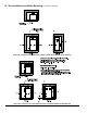
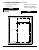
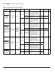
Figure 2C: Wall Mounting Hole Location / Layout
TOP EDGE OF BOILER
'HOLE C'
'HOLE A'
'HOLE D'
LEFT SIDE OF BOILER
1.0" MIN. CLEARANCE TO COMBUSTIBLE
10.0" MIN. CLEARANCE TO COMBUSTIBLES
16
25
3
4
WALL MOUNTING BRACKET
CENTER LINE
BOTTOM SECURING
BRACKET CENTER LINE
2.0" MIN. CLEARANCE TO COMBUSTIBLE
'HOLE B'
3
16
" DIA. PILOT HOLES
FOR
5
16
" LAG SCREWS
(4 PLACES)
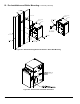
m. See Section IV Venting; Paragraph B, 5 “Field
Installation of CPVC Vent Pipe - Wall Mounted
Boiler Builds” for instructions on attaching the
vent system to the boiler.
WARNING
Vent pipe must be inserted rmly into vent
connector and secured by tightening the metal
strap worm screw.
III. Pre-Installation and Boiler Mounting G. General (continued)
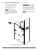
n. After the boiler has been piped, wired, connected
to vent and combustion air system piping and
combustion performance testing completed per
Section IX “System Start-up”, install Access
Panel/Gasket assembly and secure with provided
four #8 x ½” black oxide Phillips head sheet
metal screws. See Figure 2E “access Panel and
Gasket Installation”.
WARNING
Access Panel must be installed while boiler is in
operation.