
Alpine Installation, Operating, and Service Instructions


103448-02 - 6/13 59
VI. Water Piping and Trim C. Standard Installation Requirements (continued)
9. Isolation Valves (Strongly recommended) –
Isolation valves are useful when the boiler must be
drained, as they will eliminate having to drain and
rell the entire system.
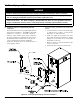
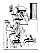
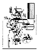
10. Drain Valve (Required) – Drain valve is packaged
loose with boiler and must be installed in the
location shown in Figure 36 “Factory Supplied
Piping and Trim Installation” of the Installation,
Operating and Service Instructions.
11. Low Water Cutoff (Required by some Codes) –
LWCO with harness is available as optional kit.
Order Complete Kit (Part Number 102097-01) when
required.
D. Special Situation Installation Requirements
Observe the following guidelines when making the
actual installation of the boiler piping for special
situations:
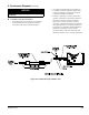
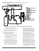
1. Systems containing high level of dissolved oxygen
– Many hydronic systems contain enough dissolved
oxygen to cause severe corrosion damage to Alpine
(ALP) boiler heat exchanger. Some examples
include but not limited to:
• Radiant systems employing tubing without
oxygen barrier
• Systems with routine additions of fresh water
• Systems open to atmosphere
If the boiler is used in such a system, it must be
separated from oxygenated water being heated with
a heat exchanger as shown in Figure 39. Consult
the heat exchanger manufacturer for proper heat
exchanger sizing as well as ow and temperature
requirements. All components on the oxygenated
side of the heat exchanger, such as the pump
and expansion tank, must be designed for use in
oxygenated water.
2. Piping with a Chiller - If the boiler is used in
conjunction with a chiller, pipe the boiler and chiller
in parallel. Use isolation valves to prevent chilled
water from entering the boiler.
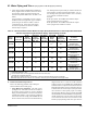
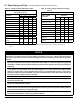
Table 19: Multiple Boiler Water Manifold Sizing
Boiler Model
Number of Boilers
2 3 4 5 6 7 8
Recommended Minimum Common Water
Manifold Size (NPT)
ALP080B 1¼” 1½” 1½” 2” 2” 2” 2½”
ALP105B 1¼” 1½” 2” 2” 2½” 2½” 2½”
ALP150B 1½” 2” 2½” 3” 3” 3” 3”
ALP210B 2” 2½” 2½” 3” 3½” 3½” 3½”
ALP285B 2” 3” 3” 3½” 4” 4” 5”
ALP399 2½” 3” 3” 4” 5” 5” 5”
of the discharge pipe must terminate in an unthreaded
pipe. If the relief valve is not piped to a drain, it must
terminate at least 6” above the oor. Do not run relief
valve discharge piping through an area prone to
freezing. The termination of discharge piping must be
in an area where it will not become plugged by debris.
WARNING
Safety relief valve discharge piping must be
piped such that the potential of severe burns
is eliminated. DO NOT pipe in any area where
freezing could occur. DO NOT install any shut-off
valves, plugs or caps. Consult Local Codes for
proper discharge piping arrangement.
2 Circulator (Required) – Usually at least two
circulators will be required to properly install a
Alpine™ Series boiler. See Paragraph B above for
information on sizing the circulators.
3. Expansion Tank (Required) – If this boiler is
replacing an existing boiler with no other changes
in the system, the old expansion tank can generally
be reused. If the expansion tank must be replaced,
consult the expansion tank manufacturer’s literature
for proper sizing.
4. Fill Valve (Required) – Either manual
(recommended) or automatic ll valve may be used.
However, if automatic rell is employed, a water
meter must be added to evaluate the makeup water
volume taken after initial ll and eliminate any
water leakage as early as possible.
5. Automatic Air Vent (Required) –At least one
automatic air vent is required. Manual vents will
usually be required in other parts of the system to
remove air during initial ll.
6. Manual Reset High Limit (Required by some
Codes) – This control is required by ASME CSD-1
and some other codes. Install the high limit in the
boiler supply piping just above the boiler with no
intervening valves. Set the manual reset high limit
to 200°F. Wire the limit per Figures 43 and 45A in
Section VIII Electrical.
7. Flow Control Valve (Strongly Recommended) –
The ow control valve prevents ow through the
system unless the circulator is operating. Flow
control valves are used to prevent gravity circulation
or “ghost ows” in circulator zone systems through
zones that are not calling for heat.
8. Y-strainer (Recommended) – A Y-strainer or
equivalent strainer removes heating system debris
from hydronic systems and protects boiler heat
exchanger from fouling up. Install the strainer
downstream of full port isolation valve, at the inlet
side of the circulator, for easy service.