
Alpine Installation, Operating, and Service Instructions


103448-02 - 6/13 87
WARNING
These instructions include a procedure for
adjusting the air-fuel mixture on this boiler.
This procedure requires a combustion analyzer
to measure the CO
2
(or Oxygen) and Carbon
Monoxide (CO) levels in ue gas. Adjusting the
air-fuel mixture without a proper combustion
analyzer could result in unreliable boiler operation,
personal injury, or death due to carbon monoxide
poisoning.
4. While the burner is at high re adjust the throttle
as needed to obtain the CO
2
(or O
2
) settings shown
in the Table 26 (for natural gas) or Table 27 (for LP
gas):
• To reduce the CO
2
(increase the O
2
) turn the
throttle clockwise
• To increase the CO
2
(reduce the O
2
) turn the
throttle counter-clockwise
Make adjustments in increments of 1/8 to 1/4 turn
and allow the boiler at least a minute to respond to
each adjustment before making another. In general,
the CO level will be at its lowest somewhere in the
CO
2
range shown in this table.
5. Verify that the gas inlet pressure is between the
upper and lower limits shown in Table 24 with all
gas appliances (including the converted boiler) both
on and off.
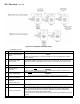
6. To lock the boiler in low re, select “Low” from
manual control screen. If measured % O
2
on LF,
is out of spec (see Table 26 or 27), then turn offset
screw clockwise (see Figure 53) to lower % O
2
or
vice versa.
WARNING
Offset screw on each Alpine Series boiler is
adjusted at the factory to the specication. DO
NOT touch the offset screw if measured 0
2
on Low
Fire is in the spec (see Table 26 or 27).
7. If the boiler is converted from natural to LP gas then
use a label sheet which is provided with the boiler
for conversions from natural to LP gas. Otherwise
skip this Step and proceed to Step 8. Once
conversion is completed, apply labels as follows:
• Apply the “Rating Plate Label” adjacent to the
rating plate.
• Apply the “Gas Valve Label” to a conspicuous
area on the gas valve.
• Apply the “Boiler Conversion Label” to a
conspicuous surface on, or adjacent to, the outer
boiler jacket. Fill in the date of the conversion
and the name and address of the company
making the conversion with a permanent marker.
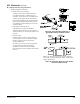
8. Install Flue Temperature Sensor into:
• Flue sensor port of boiler CPVC/PVC two-pipe
vent system connector (oor standing build) -
See Figures 6 and 17.
• Flue sensor port of vent elbow, located inside air
box behind access panel (wall hung build) - see
Figure 7B.
• Flue sensor port of boiler concentric vent collar
(oor standing build) - see Figure 18.
9. Install Access Panel/Gasket Assembly as shown in
Figure 2E.
WARNING
Access Panel must be installed after the vent
pipe is fully secured into the vent elbow. Failure
to properly secure the vent into the elbow with
clamp, could lead to property damage, personal
injury or loss of life.
N. Test External Limits
Test any external limits or other controls in accordance
with the manufacturer’s instructions.
O. Check Thermostat Operation
Verify that the boiler starts and stops in response to
calls for heat from the heating thermostat and indirect
water heater thermostat. Make sure that the appropriate
circulators also start and stop in response to the
thermostats.
P. Adjust Supply Water Temperature
As shipped, the heating set point supply temperature is
set to 180°F and, indirect water heater set point supply
temperature is set to 170°F. If necessary, adjust these to
the appropriate settings for the type of system to which
this boiler is connected. See Section X “Operation”
(parameter Table on page 107) of this manual for
information on how to do this.
Boiler
Model
Altitude Range
0 - 7000 Ft.
% CO
2
% O
2
Range CO, PPM
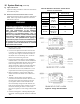
ALP080B
11.4 - 9.5
(High Fire)
11.4 - 9.1
(Low Fire)
3.5 - 6.5
(High Fire)
3.5 - 7.0
(Low Fire)
Less than
100 PPM
ALP105B
ALP150B
ALP210B
ALP285B
ALP399
Table 27: Typical Combustion Values, LP Gas
IX. System Start-up (continued)