IN S TAL L AT ION , OP E R AT IN G AN D S E R V IC E IN S T R U C T ION S F OR M P O® 3 - PA S S O I L B O I L E R F o r s e rvi c e o r re p a i r s to b o i le r, c a ll yo ur he a ti ng c o ntr a c to r o r o i l s up p li e r. W he n s e e k i ng i nfo rma ti o n o n b o i le r, p r o vi d e B o i le r Mo d e l Numb e r a nd S e ri a l Num b e r a s s ho wn o n Ra ti ng L a b e l lo c a te d o n to p o f the b o i le r.
IMPORTANT INFORMATION - READ CAREFULLY All boilers must be installed in accordance with National, State and Local Plumbing, Heating and Electrical Codes and the regulations of the serving utilities. These Codes and Regulations may differ from this instruction manual. Authorities having jurisdiction should be consulted before installations are made. In all cases, reference should be made to the following Standards: USA BOILERS A.
DANGER DO NOT store or use gasoline or other flammable vapors or liquids in the vicinity of this or any other appliance. WARNING Improper installation, adjustment, alteration, service or maintenance can cause property damage, personal injury or loss of life. Failure to follow all instructions in the proper order can cause personal injury or death.
WARNING This boiler contains very hot water under high pressure. Do not unscrew any pipe fittings nor attempt to disconnect any components of this boiler without positively assuring the water is cool and has no pressure. Always wear protective clothing and equipment when installing, starting up or servicing this boiler to prevent scald injuries. Do not rely on the pressure and temperature gauges to determine the temperature and pressure of the boiler.
TABLE OF CONTENTS I. Pre-Installation ................................................ 8 IX. Oil Piping ......................................................... 48 II. Packaged Boiler Assy. - Trim & Controls ......... 11 X. System Start-Up .............................................. 50 III. Unit-Pak Boiler Assy. - Trim & Controls............ 23 XI. Maintenance & Service Instructions ................ 62 IV. Water Boiler Piping .......................................... 30 XII. Boiler Cleaning .
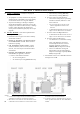
Figure 1: MPO 84 Thru MPO 231 Water Boiler
28-5/8” 34-5/8” MPO189 MPO231 36” 30” 24” 7” 6” 6” 5” 5” “C” 17.84 14.46 11.08 7.70 7.70 Water Content - Gallons 0.60 0.82 1.05 1.35 1.65 MPO115 MPO147 MPOI89 MPO231 GPH MPO84 Boiler Model No. 231 189 147 115 84 MBH 203 167 129 101 74 DOE Heating Capacity MBH Burner Capacity TABLE 1B: RATING DATA 177 145 112 87 64 Water MBH I=B=R NET Ratings 7 7 6 6 6 8x8 8x8 8x8 8x8 8x8 15 15 15 15 15 Round Rectangle Height In. Dia. In. x In. Ft. 771 34.
SECTION I: PRE-INSTALLATION A. INSPECT SHIPMENT carefully for any signs of damage. 1. All equipment is carefully manufactured, inspected and packed. Our responsibility ceases upon delivery of crated boiler to the carrier in good condition. 2. Any claims for damage or shortage in shipment must be filed immediately against the carrier by the consignee. No claims for variances from, or shortage in orders, will be allowed by the manufacturer unless presented within sixty (60) days after receipt of goods. B.
NOTICE Clearance to venting is for single wall vent pipe. If Type L vent is used, clearance may be reduced to the minimum required by the vent pipe manufacturer. C. PROVIDE COMBUSTION AND VENTILATION AIR. Local and National Codes may apply and should be referenced. WARNING Adequate combustion and ventilation air must be provided to assure proper combustion and to maintain safe ambient air temperatures. Do not install boiler where gasoline or other flammable vapors or liquids, or sources of hydrocarbons (i.
with additional space(s) of sufficient volume such that combined volume of all spaces meet criteria for unconfined space. Size each opening for minimum free area of 1 square inch per 1,000 BTU per hour input of all equipment in spaces, but not less than 100 square inches. 6. Louvers and Grilles of Ventilation Ducts a. All outside openings should be screened and louvered. Screens used should not be smaller than 1/4 inch mesh. Louvers will prevent the entrance of rain and snow. b.
SECTION II: PACKAGED BOILER ASSEMBLY - TRIM & CONTROLS A. REMOVE CRATE. 1. Remove all fasteners at crate skid. 2. Lift outside container and remove all other inside protective spacers and bracing. Remove miscellaneous parts carton. B. REMOVE BOILER FROM SKID. 1. To reduce the risk of damage to boiler jacket, use the following procedure to remove from skid, see Figure 3: Step 1. Boiler is secured to base with (4) 5/16" cap screws, (2) in front and (2) in rear of shipping skid, see Figure 3.
Figure 4A: Partial Front View - Burner Swing Door Mounted to Boiler - Fully Closed and Secured Step 2. Loosen and remove right side latching hardware (3/8" x 1-3/4" lg. tap bolt and washer). Step 3. Remove left side latching hardware (3/8" x 1-3/4" lg. tap bolt and washer). Step 4. Disconnect burner power cord from receptacle located in lower right corner of jacket front panel. Step 5.
Figure 4B: Top View - Burner Swing Door Mounted to Cast Iron Block Assembly (Jacket Removed for Clarity) 13
(protruding from the bottom of the front section casting - see Figure 4A). E. INSPECT SWING DOOR INSULATION AND ROPE GASKET. Step 3. Use one hand to help hold door in position by lifting up on rear burner housing or applying pressure directly to the door while re-installing the securing hardware with your opposite hand. Always install right side latching hardware (3/8"-16 x 1-3/4" lg. tap bolt and flat washer) first, then install left side hinge hardware (3/8"-16 x 1-3/4" lg.
5 thru 12) throughout the assembly sequence outlined below as it applies to your installation. 1. Install supply manifold and aquastat control, refer to Figure 5. Step a. Remove two (2) #8 x 1/2" lg. sheet metal screws securing jacket top rear panel to jacket rear panel. Slightly lift and pull jacket top rear panel away from jacket top panel to gain access to internal J-box wiring harness. Step b. Locate the cast iron supply manifold shown in Figure 5. Apply thread sealant to 1-1/2" NPT male threads.
Figure 6: Internal Junction Box and Wiring Harness Details Mount the control box on the probe by aligning the keyhole slots with the probe mounting screws. Replace the wing nut. Secure the control box by tightening wing nut and two (2) mounting screws. Step c. Remove snap-in plug from 7/8" dia. center knockout, adjacent to aquastat control harness. Step d. Insert three (3) wires with Molex connector located on opposite end of LWCO harness through 7/8" dia. knockout.
Figure 7: Optional Equipment - Low Water Cut-Off (LWCO) Control Assembly Details Figure 8: Optional Equipment - Auxiliary Limit Control Assembly Details from auxiliary limit control with harness socket connector. Push connectors together until snap, on side of connector, is locked in place. 4. Install return manifold and relief valve, refer to Figure 9. Step a. Locate the cast iron return manifold with injector nipple (installed). Apply thread sealant to 2" NPT male threads.
Place a wrench on the hex nut portion and tighten manifold until the return pipe orientation is correct for your installation and the joint is water tight. Step b. Install relief valve using 3/4" NPT tapping on side of return manifold. Relief valve must be installed in vertical position. If orientation of return manifold is for: • 1-1/2" NPT vertical return piping - Install 3/4" NPT x 90° street ell (not furnished) into either the left or right side tapping on return manifold.
these fittings, determine if drain valve is to be located on the left or right side. Tighten nipple and tee into 1-1/4" NPT lower rear tapping on rear section until joints are water tight for desired position. Step c. Apply sealant to 3/4" NPT thread on drain valve. Thread into 3/4" NPT tapping on side outlet of tee. Use hex nut portion to tighten valve until water tight. Step d. If an Alliance SL™ water heater is connected to system, do not install 1-1/4" NPT pipe plug.
NOTE: Read caution statement before proceeding. • Model MPO84 - To install flueway baffle in 3rd pass on left side of boiler, hold baffle with word "Left" readable at the top. Slide baffle in flueway until position tab touches fins on left side of 3rd pass flueway. To install flueway baffle in 3rd pass flueway on right side of boiler, hold baffle with word "Right" readable at the top. Slide baffle in flueway until position tab touches fins on right side of 3rd pass flueway.
• Models MPO147, MPO189 and MPO231 - To install flueway baffle in 2nd pass flueway on left side of boiler, hold baffle with word "Left" readable at the top. Slide baffle in flueway until position tab touches fins on right side of 2nd pass flueway. To install flueway baffle in 2nd pass flueway on right side of boiler, hold baffle with word "Right" readable at the top. Slide baffle in flueway until position tab touches fins on left side of 2nd pass flueway.
ii. Installation: • To insert drawer assembly, reverse the procedure in Item i above. b. Check factory installed oil nozzle for size and type. Refer to Table 13 for details. If nozzle needs replacement, follow steps below. Also refer to Figure 41B. i. Remove the nozzle adapter (2) from the drawer assembly by loosening the screw (1). ii. Remove existing nozzle from nozzle adapter. iii. Insert the proper nozzle into nozzle adapter and tighten securely. (Do not over tighten). iv.
SECTION III: UNIT-PAK BOILER ASSEMBLY - TRIM & CONTROLS MPO® Unit-Pak Boiler Assembly Shipment Content Check List (see Figure 13) 1. ___ Cast Iron Section/Burner Swing Door/Smoke Box Assembly Mounted on Shipping Skid: ____ MPO2 – Part # 100032-01 / 100045-01 / 100021-01 ____ MPO3 – Part # 100032-02 / 100045-01 / 100021-01 ____ MPO4 – Part # 100032-03 / 100045-01 / 100021-01 ____ MPO5 – Part # 100032-04 / 100045-02 / 100021-01 2.
A. REMOVAL OF CAST IRON SECTION/ BURNER SWING DOOR / SMOKE BOX ASSEMBLY FROM SKID. WARNING The Cast Iron Section/Burner Swing Door/Smoke Box Assembly has a substantial weight. Insure the travel path to permanent location, as well as mounting surface at boiler permanent location, are structurally sound and rated to handle the boiler weight and water content (refer to Table 1A). Otherwise, a potentially hazardous situation could result in death, serious injury and substantial property damage. 1.
Figure 14: Boiler Removal from Skid
3. Locate Hardware Bag, remove two 5/16”-18 x ½” Phillips pan head machine screws. 4. Place front jacket panel over front section attachment bosses and align jacket holes with front section boss holes. 5. Firstly, install two 5/16”-18 x ½” Phillips pan head machine screws hand tight to secure front jacket panel right side to casting 6.
b. Lift door upward into the build-in cast ramp/door rest (protruding from the bottom of the front section casting – see Figure 15). c. Use one hand to apply pressure directly to the door to hold it in closed position while reinstalling earlier removed door-latching hardware (3/8”-16 x 1-3/4” tap bolt and 5/16” washer).
100% WITHOUT USING THE ALTERNATING METHOD DESCRIBED ABOVE. See Figure 16. e. Failure to follow the prescribed procedure could cause thread damage to casting and /or leak at the door seal. IF LEFT SIDE TAP BOLT IS TIGHTENED BEFORE RIGHT SIDE TAP BOLT, RIGHT SIDE OF THE DOOR CAN NOT BE DRAWN-IN TO PROVIDE AN AIRTIGHT SEAL, as shown in Figure 17. Applying excessive torque will only cause thread damage. F. JACKET REAR PANEL INSTALLATION. 1.
hex head cap screws hand tight, then, alternately tighten them with open end or socket wrench. 6. Repeat above steps with right Cleanout Cover. 7. Apply the adhesive sealant to the underside of the collar, all around, at the inside corner of the collar outer ring. Insure adhesive bead is complete all around and without gaps. 8. Place the collar over smokebox tongue and align collar integral mounting ear slots with smokebox bosses. 9.
SECTION IV: WATER BOILER PIPING NOTICE Failure to pipe boiler as specified in this manual may result in excessive system noise. A. EVALUATE THE EXISTING WATER SYSTEM. Design a piping system and install boiler which will prevent oxygen contamination of boiler water and frequent water additions. 1. There are many possible causes of oxygen contamination such as: a. Addition of excessive make-up water as a result of system leaks. b. Absorption through open tanks and fittings. c.
Figure 18A: Recommended Water Piping for Circulator Zoned Heating Systems
Figure 18B: Recommended Water Piping for Zone Valve Zoned Heating Systems
5. If it is required to perform a long term pressure test of the hydronic system, the boiler should first be isolated to avoid a pressure loss due to the escape of air trapped must first be removed from the boiler. A loss of pressure during such a test, with no visible water leakage, is an indication that the boiler contained trapped air. To perform a long term pressure test including the boiler, ALL trapped air must first be removed from the boiler.
SECTION V: INDIRECT WATER HEATER PIPING A. CONNECT an Alliance SL™ WATER HEATER PIPING as shown in Figures 20A and 20B. Also refer to Figures 18A and 18B. 1. Refer to Alliance SL™ instructions for additional information.
SECTION VI: VENTING A. CHIMNEY VENTING 1. Chimney venting is an important part of a safe and efficient oil fired appliance system. Contact your local fire and building officials on specific requirements for restrictions and the installation of fuel oil burning equipment.
Figure 21: Recommended Vent Pipe Arrangement and Chimney Requirements Figure 22: Proper and Improper Locations of Draft Regulator 36
2. Type B Chimney Connector - a type B chimney connector can be used to transmit the flue gases provided flue gas temperature entering the chimney connector is greater than 310°F. 3. Type L Chimney Connector - a type L vent or other suitable material shall be used for a chimney connector if the temperature or exiting temperature is less than 310°F. 2. NFPA 31 and CSA B139-04 have information to help the installer make an appropriate choice of venting materials.
WARNING WARNING Remove the baffles if there are any signs of condensation in the chimney or chimney connector. Consult with your local chimney professional for recommendations. Using outdoor air in the middle of winter may result in lower stack temperatures and chimney degradation. Any signs of condensate seepage or discoloration at the base of chimney must be remedied immediately per the details outlined in this section. E.
SECTION VII: DIRECT VENTING / AIR INTAKE PIPING A. GENERAL GUIDELINES 1. Direct Vent system must be installed in accordance with these instructions and applicable provisions of local building codes. Contact your local fire and building officials on specific requirements for restrictions and the installation of fuel oil burning equipment.
Figure 24: Vent Terminal Location TABLE 4: WALL CUTOUT DIMENSIONS Boiler Model No. Direct Vent Conversion Kit Part No. "L" Dimension (Inch) MPO147 MPO189 102130-02 8¼ MPO231 1021300-03 9¼ c. Fasten the vent hood body to the outside wall with appropriate fasteners (installer provided). d. Seal the edges of the vent hood base plate to the wall with a high-temperature silicone sealant (provided in Bagged Hardware). e.
For installations in Canada, follow requirements of CSA B139 – Installation Code for Oil-Burning Equipment, latest edition. 2. A vent pipe connector, designed for positive pressure venting, shall be supported for the design and weight of material employed, to maintain clearances, prevent physical damage and separation of joints. All joints MUST BE sealed, for positive vent pressure, to prevent flue gas leakage into the structure. 3.
Figure 29: Appliance Adapter Installation E. CONNECTING APPLIANCE ADAPTER TO BOILER FLUE OUTLET COLLAR (See Figure 29) 1. Apply a bead of supplied high temperature sealant to boiler flue outlet collar approximately 1" from collar end. 2. Remove any oil and grease from inside of supplied Appliance (Boiler Flue Outlet) Adapter, and, apply a bead of high temperature sealant to inside of the adapter, ½" from end. 3. With twisting motion, assemble the appliance adapter onto boiler flue outlet collar. 4.
Figure 31: Vent Pipe Ends, Vent Termination and Appliance Adapter Sealing secondly, at vent pipe side to be connected to the appliance (boiler outlet collar) adapter. See Figure 30. 5. Slide supplied Cover Rings; firstly, over stop bead on vent termination inner pipe; secondly, over stop bead on appliance adapter. See Figure 30. 6. Remove any oil and grease from the end of vent termination inner pipe, and, from the end of the appliance adapter. 7.
10. Secure the tee to the pipe with at least (3) sheet metal screws (installer provided) evenly spaced. WARNING DO NOT reduce size of air intake pipe. 3. Start at burner and work towards Direct Vent termination air intake. 4. Remove burner cover. Loosen two screws securing outside air duct bracket to burner cover mounting plate. See Figure 33. 5. Procure a 2-ft section of 4" diameter galvanized single wall vent pipe, cut off the crimped pipe end below stop bead. 6.
SECTION VIII: ELECTRICAL DANGER Positively assure all electrical connections are unpowered before attempting installation or service of electrical components or connections of the boiler or building. Lock out all electrical boxes with padlock once power is turned off. WARNING Failure to properly wire electrical connections to the boiler may result in serious physical harm. Electrical power may be from more than one source. Make sure all power is off before attempting any electrical work.
A call for heat by the thermostat energizes the L7248C control which in turn energizes the primary control to turn on the burner. The burner will operate in the following sequence: Prepurge for the first 10 seconds; fire until the thermostat is satisfied or the limit setting on the operating (high) limit is reached; post-purge for the last 10 seconds. The circulator will operate as long as the thermostat is calling for heat.
Figure 34B: Schematic Wiring Diagram, Water Boiler With Riello Burner (Natural Draft Only)
SECTION IX: OIL PIPING A. GENERAL WARNING 1. Use flexible oil line(s) so the burner swing door can be opened without disconnecting the oil supply piping. Under no circumstances can copper with sweat style connectors be used. 2. A supply line fuel oil filter is recommended as a minimum for all firing rates but a pleated paper fuel oil filter is recommended for the firing rates below 1.0 GPH to prevent nozzle fouling. NOTICE 3. Use Flared fittings only. Cast iron fittings cannot be used.
C. TWO PIPE OIL LINES 1. For two piped systems, where more lift is required, the two-stage fuel unit is recommended. Table 6 (two-stage) and Table 7 (single-stage) show allowable lift and lengths of 3/8 inch and 1/2 inch OD tubing for both suction and return lines. Refer to Figure 36. 2. Follow the oil pump manufacturer’s recommendations on the proper connections for a two pipe system. Some manufacturers require the insertion of a bypass plug.
SECTION X: SYSTEM START-UP WARNING All boilers equipped with burner swing door have a potential hazard which can cause severe property damage, personal injury or loss of life if ignored. Before opening swing door, turn off service switch to boiler to prevent accidental firing of burner outside the combustion chamber. Be sure to tighten swing door fastener completely when service is completed. In addition, the burner power cord will have to be disconnected from the receptacle in the front jacket. A.
2. PRESS RED RESET BUTTON on front of burner cover (Beckett, Riello burners), hold button for one (1) second and release to reset primary control. 3. On WATER BOILERS WITHOUT TANKLESS HEATERS equipped with L7248 electronic aquastat controller, set High Limit (HL) at 180°F. This temperature can be varied to suit installation requirements. L7248 controller has the High Limit adjustment range from 180°F to 240°F (82°C to 116°C). High Limit Differential is fixed at 15°F (8°C). 4.
TABLE 9: L7248 CONTROLLER OPERATING SEQUENCE Action System Response Thermostat calls for heat. Circulator starts when water temperature is above Low Limit setting (if applicable). Boiler temperature is checked. Burner starts when water temperature is below High Limit setting. Boiler exceeds the High Limit. Burner is turned off. Burner restarts when the water temperature drops below the High Limit setting minus the Differential. Thermostat is satisfied. Circulator and burner turn off.
NOTE: For Primary Control "Pump Priming Cycle" details, see Paragraph I, No. 2., Step a., Item ii . 4. Close vent fitting and burner flame should start immediately after prepurge is completed. Prepurge prevents burner flame until 15 seconds has elapsed after initial power is applied to burner. During prepurge the motor and igniter will operate but the oil valve will remain closed. Refer to Oil Primary Control Instructions for more details. 5. Adjust oil pressure. a.
Figure 41: "L1/L2" and "V1" Head Electrode Positioning and Gun Setting (Beckett AFG)
Figure 41A: Installation/Removal of Drawer Assembly Figure 41B: Nozzle Replacement Figure 41C: Turbulator Setting Figure 41D: Electrode Positioning (Riello 40 Series) Figure 41E: Pump Connections and Port Identification 55
6. Loosen the two screws securing the rear door, then, swing to the right and down. WARNING Do not attempt to start the burner when excess oil has accumulated, when the unit is full of vapor, or when the combustion chamber is very hot. Direct Vent Application H. CHECK/ADJUST OIL BURNER BEFORE STARTING. VERIFY BURNER SETTINGS - refer to Table 10 . 1. Turn off power to burner before proceeding. 7. Loosen splined nut. 8.
Note: For Primary Control “Pump Priming Cycle” details see Paragraph I, No. 2, Step a, Item ii. The zero calibration has been factory set; the upper left acorn nut locks retention head at “0” position. If the zero calibration has to be reset, follow the adjustment procedure, outlined at “Prepare Burner & Site” section of Beckett Model NX Oil Burner Instruction Manual, Form Number 610BNX.
operating condition. If flame appears stringy instead of solid fire, try another nozzle of the same type. 2. The plate setting number has been factory preset to obtain an initial CO2 range of 11.0 – 11.5 % at burner start-up. Adjusting head/air plate forward (the pointer will move towards “0” scale number) reduces excess air and increases % CO2. Adjusting head/air plate rearwards (the pointer will move towards “5” scale number) increases excess air and reduces % CO2. See Figure 45. 3.
• Flashing at 1 Hz (½ second on, ½ second off): system is locked out or in Restricted Mode. • Flashing at ¼ Hz (2 seconds on, 2 seconds off): control is in Recycle Mode. • On: cad cell is sensing flame. • Off: cad cell is not sensing flame. vii. Cad Cell Resistance Check: For proper operation it is important that the cad cell resistance is below 1600 ohms. During a normal call for heat, once the control has entered the Run Mode, press and release the reset button.
v. Power Failure Check: After Flame is established, turn the power off to the control/ burner. The burner should shut down safely. When power is restored a normal ignition sequence should be started. 3. WARNING — Check High Limit Control — Jumper Thermostat Terminals. Allow burner to operate until shut-down by limit. Installation is not considered complete until this check has been made. WARNING Jumper must be removed after this check. 4.
Important Product Safety Information Refractory Ceramic Fiber Product Warning: The Repair Parts list designates parts that contain refractory ceramic fibers (RCF). RCF has been classified as a possible human carcinogen. When exposed to temperatures about 1805°F, such as during direct flame contact, RCF changes into crystalline silica, a known carcinogen. When disturbed as a result of servicing or repair, these substances become airborne and, if inhaled, may be hazardous to your health.
SECTION XI: MAINTENANCE AND SERVICE INSTRUCTIONS A. MAINTENANCE OF LOW WATER CUTOFF DEVICES (when installed) See Section XV Appendix for LWCO Installation Instructions. WARNING Probe type low water cut-off devices require annual inspection and maintenance. 1. PROBE TYPE LOW WATER CUT-OFF Although these devices are solid state in their operation, the probe is exposed to possible contamination in the boiler water and subject to fouling. Provisions have been made on the supply manifold on the boiler.
DANGER Assure that the boiler is at zero pressure before removing the relief valve. Open the safety valve to relieve all internal pressure prior to proceeding. Safety valve discharge piping must be piped such that the potential for burns is eliminated. c. Remove relief valve using extreme care to avoid damaging it. d. Add an appropriate amount of recommended boil out compound. e. Replace relief valve. f. Fill the entire system with water. g. Start firing the boiler. h.
SECTION XII: BOILER CLEANING WARNING All boiler cleaning must be completed with burner service switch turned off. Boilers equipped with burner swing door have a potential hazard which can cause severe property damage, personal injury or loss of life if ignored. Before opening swing door, turn off service switch to boiler to prevent accidental firing of burner outside the combustion chamber. Disconnect the burner plug from the receptacle in the front jacket.
Figure 49: Cleaning of Boiler Flueways WARNING The boiler must be connected to an approved chimney in good condition. Serious property damage could result if the boiler is connected to a dirty or inadequate chimney. The interior of the chimney flue must be inspected and cleaned before the start of the heating season and should be inspected periodically throughout the heating season for any obstructions.
SECTION XIII: TROUBLE SHOOTING A. COMBUSTION 1. NOZZLES — Although the nozzle is a relatively inexpensive device, its function is critical to the successful operation of the oil burner. The selection of the nozzle supplied with the MPO boiler is the result of extensive testing to obtain the best flame shape and efficient combustion. Other brands of the same spray angle and spray pattern may be used but may not perform at the expected level of CO2 and smoke.
d. Excessive airflow or draft causing flame to leave burner head. Note: The Safety Monitoring Circuit (SMC) is designed to provide lockout in the event of a stuck or welded motor relay. e. Excessive back pressure causing flame to be erratic. NOTICE 3. Control locks out after Trial For Ignition (TFI). a. No oil to burner. If flame is not established within 15 seconds of oil valve actuation (known as Trial For Ignition [TFI]) lockout will occur.
Bare Boiler Assembly
Item Description No. Part No. MPO84 MPO115 MPO147 MPO189 MPO231 1. BARE BOILER ASSEMBLY 1A Front Section, Machined 100060-01 1 1 1 1 1 1B Center Section, Machined 100061-01 --- --- 1 2 3 1C Rear Section, Machined 100062-01 1 1 1 1 1 1D Slip Nipple, 22-B Steel 806600375 2 2 4 6 8 Upper Tie Rod, 3/8"-16 x 10" Lg. 80861071 1 1 --- --- --- Upper Tie Rod, 3/8"-16 x 16" Lg. 80861075 --- --- 1 --- --- Upper Tie Rod, 3/8"-16 x 21-1/2" Lg.
Bare Boiler Assembly
Item Description No. Part No. MPO84 MPO115 MPO147 MPO189 MPO231 1. BARE BOILER ASSEMBLY (Continued) Burner Swing Door Insulation (Less Pockets) 100039-01 1 1 1 1 --- Burner Swing Door Insulation (With Pockets) 100039-02 --- --- --- --- 1 1T 5/8" Dia. Rope Gasket - Burner Swing Door 100097-01 1 1 1 1 1 1U 1/8" Dia. Rope Gasket - Observation Port 100096-01 1 1 1 1 1 1V Observation Port Cover 100074-01 1 1 1 1 1 1X 5/16"-18 x 5/8" Lg.
Jacket Assembly
Item Description No. Part No. MPO84 MPO115 MPO147 MPO189 MPO231 2.
MPO84 Thru MPO231 Water Boilers - Trim and Controls
Item No. Description Part No. MPO84 MPO115 MPO147 MPO189 MPO231 3. MPO84 Thru MPO231 WATER BOILERS - TRIM AND CONTROLS Beckett AFG Oil Burner w/Gasket for: Natural Draft MPO84 Spec No. BCB7702 100052-01 1 --- --- --- --- MPO115 Spec No. BCB7707 102065-01 --- 1 --- --- --- MPO147 Spec No. BCB7703 100053-01 --- --- 1 --- --- MPO189 Spec No. BCB7704 100054-01 --- --- --- 1 --- MPO231 Spec No. BCB7705 100055-01 --- --- --- --- 1 Spec No.
Item No. Description Part No. MPO147 MPO189 MPO231 Direct Vent Conversion Kit 102130-02 1 1 --- Direct Vent Conversion Kit 102130-03 --- --- 1 Adapter, Appliance, FDVS, 5-6 100234-02 1 1 --- Adapter, Appliance, FDVS, 6-7 100234-03 --- --- 1 Clamp, 6" Appliance, FDVS-6, Half 100235-02 2 2 --- Clamp, 7" Appliance, FDVS-7, Half 100235-03 --- --- 2 Assy., Cover Sleeve, FDVS-5 100236-02 2 2 --- Assy., Cover Sleeve, FDVS-6 100236-03 --- --- 2 Assy.
Beckett AFG Burner
BECKETT OIL BURNER PART NOS. FOR MPO SERIES BOILERS NATURAL DRAFT APPLICATIONS NOTE: When ordering parts always give the serial and model numbers shown on the boiler and burner. Also provide the name of the part(s) and part number as listed below. Boiler Model Air Tube Combination Beckett's Spec. No.
Beckett NX Burner
BECKETT OIL BURNER PART NOS. FOR MPO SERIES BOILERS DIRECT VENT APPLICATIONS NOTE: When ordering parts always give the serial and model numbers shown on the boiler and burner. Also provide the name of the part(s) and part number as listed below. Item No.
RIELLO OIL BURNER PART NUMBERS FOR MPO SERIES BOILERS NOTE: When ordering parts always give the serial and model numbers shown on the boiler and burner. Refer to Models F3 & F5 Installation Manual, Riello 40 Series Residential Oil Burners (C6501010) or Model F10 Installation Manual, Riello 40 Series Residential Oil Burners (2902554) for an exploded view of the burner and a list of spare parts.
XV. LOW WATER CUT-OFF (LWCO) ON HOT WATER BOILERS WARNING DO NOT ATTEMPT to cut factory wires to install an aftermarket Low Water Cut Off (LWCO). Only use connections specifically identified for Low Water Cut Off. In all cases, follow the Low Water Cut Off (LWCO) manufacturer's instructions. When A low water cut-off is required to protect a hot water boiler when any connected heat distributor (radiation) is installed below the top of the hot water boiler (i.e.
Figure A2: LWCO Location
0.60 0.82 1.05 1.35 1.65 Boiler Model MPO84 MPO115 MPO147 MPO189 MPO231 AFG AFG AFG AFG AFG Burner Model 6 (1) 6 7 7 7 0.50 x 45W Delavan 0.65 x 45B Delavan 0.85 x 60B Delavan 1.10 X 60B Hago 1.35 x 60B Hago Nozzle 2 2 1 0 0 150 150 150 150 150 V1 (3) V1 (0) L1 L2 L2 2 2 2 2 2 F5 F5 F5 Air Air Pump Head Insertion Burner Shutter Band Pressure Type Depth Model (setting) (setting) (PSI) (setting) (Inch) 1.35 x 60°B Delavan 1.10 x 60°B Delavan 0.
SERVICE RECORD DATE SERVICE PERFORMED 85
SERVICE RECORD DATE 86 SERVICE PERFORMED
SERVICE RECORD DATE SERVICE PERFORMED 87
Limited Warranty FOR RESIDENTIAL CAST IRON WATER BOILERS Subject to the terms and conditions set forth below, U.S. Boiler™ Co., Inc. Lancaster, Pennsylvania hereby extends the following limited warranties to the original owner of a residential grade water boiler manufactured and shipped on or after July 1,1991: ONE YEAR LIMITED WARRANTY ON RESIDENTIAL GRADE WATER BOILERS U.S. Boiler Co., Inc.