
Install Instructions

22
ii. Installation:
• To insert drawer assembly, reverse the
procedure in Item i above.
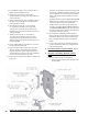
b. Check factory installed oil nozzle for size
and type. Refer to Table 13 for details.
If nozzle needs replacement, follow steps
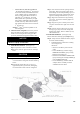
below. Also refer to Figure 41B.
i. Remove the nozzle adapter (2) from the
drawer assembly by loosening the screw
(1).
ii. Remove existing nozzle from nozzle
adapter.
iii. Insert the proper nozzle into nozzle
adapter and tighten securely. (Do not over
tighten).
iv. Replace adapter, with nozzle installed,
into drawer assembly and secure with
screw (1).
c. Inspect and measure burner electrodes.
Refer to Figure 41D for the proper electrode
settings.
d. Re-install Drawer Assembly into
Combustion Head per Step h c above.
e. Insertion Depth, verify the distance between
the tip of the end cone is equal to the
distance specified in Table 13 of this manual.
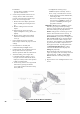
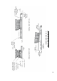
f. Turbulator Setting, refer to Figure 41C.
i. Confirm the turbulator setting is correct
for input oil nozzle installed in the burner,
readjust, if needed, to index mark specified
in Table 13 of this manual.
ii. Loosen nut (1) and turn screw (2) until the
index marker (3) is aligned with the
correct index number in the Burner Setup
Chart (Table 13).
iii. Retighten the retaining nut (1).
MODEL F5 (3 thru 5 Section): Same as
above, except, scale indicators are 0 and 4.
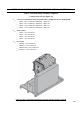
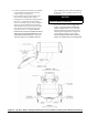
i. Pump Connections and Port Identification,
refer to Figure 41E.
This burner is shipped with the oil pump
set to operate on a single line system. To
operate on a two-line system the bypass
plug must be installed.
WARNING: Do not operate a single line system
with the by-pass plug installed. Operating a
single line system with the by-pass plug installed
will result in damage to the pump shaft seal.
NOTE: Pump pressure was factory pre-set but
must be checked at time of burner start-up. A
pressure gauge is attached to the PRESSURE/
BLEEDER PORT (7) for pressure readings. Two
PIPE CONNECTORS (4) are supplied with the
burner for connection to either a single or two-
line system. Also supplied are tow ADAPTORS
(3), two female 1/3" NPT to adapt oil lines to
burner pipe connectors. All pump port threads
are British Parallel Thread design. Direct
connection of NPT threads to the pump will
damage the pump body.
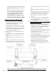
Riello manometers and vacuum gauges do not
require any adapters, and can be safely connected
to the pump ports. An NPT x metric adapter
must be used when connecting other gauge
models.
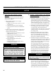
g. Replace Burner Cover and Tighten Burner Cover
Screws.
Figure 12A: Riello Oil Burner Installation