
101152-01 Installation Manual
41
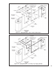
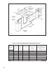
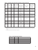
8) InstallationofVerticalExhaustTerminal-UsetheterminalsuppliedbytheventsystemmanufacturershowninTable
7.5.Attachtotheventsystem,followingtheassemblyinstructionsinthismanualforthestainlessventsystembeing
used.
9) AssemblyoftheAirIntakeSystemandAirIntakeTerminals:
a)AssembletheairintakesystemusingeithergalvanizedorPVCpipe.
b) IfPVCpipingisused,usePVCcementtoassemblethePVCintakesystemcomponents.
c)Ifgalvanizedpipingisused,useatleasttwosheetmetalscrewsperjoint.Sealtheoutsideofalljoints.
d)3”galvanizedsmokepipewilltinsidetheinletcollarontheboiler.DependingupontheexactODofthepipeused,
itmaybenecessarytocrimpthispipe.Securewithasingle#10sheetmetalscrewthroughtheholeintheinletcollar
andsealtheoutsideofthejointwithsilicone.IfPVCisusedfortheintakesystem,useashortpieceof3”galvanized
pipetoconnectthePVCtotheboiler.SiliconetheoutsideofthejointbetweenthePVCandgalvanizedpipe.
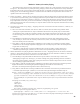
e)Horizontalintaketerminalisa90degreeelbowpointingdown.Elbowshouldprotrudethesamedistancefromthe
wallastheexhaustterminal.
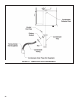
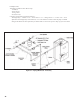
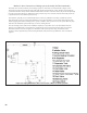
f) Verticalairintaketerminalconsistsofa180degreebend(composedoftwo90degreeelbows)asshowninFigure
7.10.
g)Installarodentscreen(notsupplied)intheinletterminal.Useascreenhaving1/2”(2x2)orlargermesh.
F. Condensate Trap and Drain Line
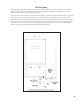
Allcondensatewhichformsintheboilerorventsystemcollectsinthesumpundertheheatexchangerandleavesthe
boilerthroughthecondensatetrap.Thistrapallowscondensatetodrainfromthesumpwhileretaininguegasesintheboiler.
ThetrapissuppliedlooseandmustbeinstalledasshowninFigure7.51.Alengthofdrainhoseissuppliedwiththeboiler
andisconnectedtothetrapasshowninFigure7.51.Notethefollowingwhendisposingofthecondensate:
a)Ifthecondensatedrainlinemustbeextended,constructtheextensionfromPVCorCPVCpipe.Insertthehose
providedwiththeboilerintotheendoftheextensionasshowninFigure7.51.
b) Condensateisslightlyacidic.Donotusemetallicpipeorttingsinthecondensatedrainline.Donotroutethedrain
linethroughareasthatcouldbedamagedbyleakingcondensate.
c)Somejurisdictionsmayrequirethatthecondensatebeneutralizedbeforebeingdisposedof.Disposeofcondensatein
accordancewithlocalcodes.
d)Donotroute,orterminate,thecondensatedrainlineinareassubjectedtofreezingtemperatures.
e)Ifthepointofcondensatedisposalisabovethetrap,itwillbenecessarytouseacondensatepumptomovethe
condensatetothedrain.Insuchcases,selectacondensatepumpthatisapprovedforusewithcondensingfurnaces.If
overowfromthispumpwouldresultinpropertydamage,selectapumpwithanoverowswitchandusethisswitch
toshutdowntheboiler.Alternatively,ifheatisanecessity,usetheoverowswitchtotriggeranalarm.
f) DonotattempttomovethetrapfromthelocationshowninFigure7.51.Donotattempttosubstituteanothertrapfor
theoneprovidedwiththeboiler.
g)TheventshowninFigure7.51mustbeleftopenforthetraptoworkproperly.
WARNING
FAILURE TO INSTALL THE CONDENSATE TRAP AND CONDENSATE DRAIN IN ACCORDANCE
WITH THE ABOVE INSTRUCTIONS COULD CAUSE FLUE GAS TO ENTER THE BUILDING,
RESULTING IN PERSONAL INJURY OR DEATH.
CAUTION
BOILER CONDENSATE IS CORROSIVE. ROUTE CONDENSATE DRAIN LINE IN A MANNER SUCH
THAT ANY CONDENSATE LEAKAGE WILL NOT CAUSE PROPERTY DAMAGE.
SOME JURISDICTIONS MAY REQUIRE THAT CONDENSATE BE NEUTRALIZED PRIOR TO
DISPOSAL.