
MPO-IQ Installation, Operating, and Service Instructions

90
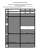
APPENDIX B – FIGURES (continued)
Figure
Number
Page
Number
Description
Section VII - Electrical
Figure 28A 42 Schematic Wiring Diagram
Figure 28B 43 Schematic Wiring Diagram, Burner Options
Figure 28C 44 Ladder Diagram
Section VIII - Oil Piping
Figure 29 45 Single Pipe Oil Line
Figure 30 46 Two Pipe Oil Lines
Section IX - System Start-Up
Figure 31A 49 R7184 Oil Primary Terminals, LED and Reset Button
Figure 31B 49 R7284 Terminals, Display and Reset Button
Figure 32 50 Cad Cell Location
Section X - Operating
Figure 33 52 Boiler Control & Option Panel Orientations
Figure 34 53 Boiler Control Key Function & Orientation
Section XII - Boiler Cleaning
Figure 35 60 Cleaning of Boiler Flueways
Figure 36 62 Boiler Control User Interface
Section XIV - Repair Parts
N/A 70 thru 80 Repair Parts