INSTALLATION, OPERATING AND SERVICE INSTRUCTIONS FOR SERIES 2PV POWER VENT GAS - FIRED BOILER For service or repairs to boiler, call your heating contractor. When seeking information on boiler, provide Boiler Model Number and Serial Number as shown on Rating Label. Boiler Model Number 20_PV_I -_ _ _ _ Boiler Serial Number Installation Date 6_ _ _ _ _ _ _ Phone Number Heating Contractor Address 8141775R12-3/01 1 Price - $3.
The following terms are used throughout this manual to bring attention to the presence of hazards of various risk levels, or to important information concerning product life. CAUTION DANGER Indicates a potentially hazardous situation which, if not avoided, may result in moderate or minor injury or property damage. Indicates an imminently hazardous situation which, if not avoided, will result in death, serious injury or substantial property damage.
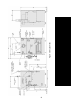
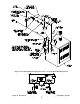
Figure 1: Elevation Views
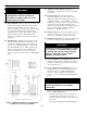
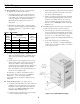
I. Pre-Installation C. Appliance is design certified for installation on WARNING combustible flooring. The boiler must not be installed on carpeting. Carefully read all instructions before installing boiler. Failure to follow all instructions in proper order can cause personal injury or death. D. Provide clearance between boiler jacket and combustible material in accordance with local fire ordinance. See Figure 2 for minimum clearance from combustible material for closet installation.
2. Determine Total Input of all appliances in space. Round result to nearest 1,000 Btu per hour (Btuh). a. Direct communication with outdoors. Minimum free area of 1 square inch per 4,000 Btu per hour input of all equipment in space. 3. Determine type of space. Divide Volume by Total Input. b. Vertical ducts. Minimum free area of 1 square inch per 4,000 Btu per hour input of all equipment in space. Duct cross-sectional area shall be same as opening free area. a.
III. Water Piping and Trim F. Space heating and domestic water heating with Alliance CAUTION water heater. Install Alliance water heater as a separate heating zone. Refer to Alliance Installation, Operating and Service Instructions for additional information. Failure to properly pipe boiler may result in improper operation and damage to boiler or building. G.
Figure 3: Recommended Boiler Piping For Series - Loop Hot Water Heating Systems Figure 4: Recommended Piping for Combination Heating & Cooling (Refrigeration) Systems 7
IV. Gas Piping A. Size gas piping. Design system to provide adequate 3. Install sediment trap, ground-joint union and manual shut-off valve upstream of boiler gas control valve and outside jacket. See Figure 6. gas supply to boiler. Consider these factors: 1. Allowable pressure drop from point of delivery to boiler. Maximum allowable system pressure is ½ psig. Actual point of delivery pressure may be less; contact gas supplier for additional information.
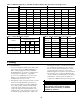
Table 2: Maximum Capacity of Schedule 40 Pipe in CFH For Gas Pressures of 0.5 psig or Less 0.3 inch w.c. Pressure Drop 0.5 inch w.c.
Table 5: Burnham Vent System Components Vent System Component Burnham *Cartoned Part Number Burnham Component Part Number 3" Dia. Pipe x 1 Ft 61160112 8116135 3" Dia. Pipe x 3 Ft 61160101 8116058 3" Dia. Pipe x 4 Ft ** 8116176 3" Dia. Pipe x 5 Ft 61160111 8116059 3" Dia. 90° Elbow 61160121 8116060 3" Dia. 45° Elbow 61160131 8116061 * * * (d) Place in operation the appliance being inspected. Follow the Lighting (or Operating) Instructions.
D. Install Vent Pipe, General. 2. Vent terminal location restricted per following: a. Minimum 12 inches above grade plus normally expected snow accumulation level, or 7 feet above grade if located adjacent to public walkway. Do not install over public walkway where local experience indicates condensate or vapor from Category III appliances creates a nuisance or hazard. 1. Start at vent connector. Work toward vent terminal. 2.
Figure 9: Recommendations for Thimble and Wall Penetration VI. Electrical A. General. Install wiring and ground boiler in Instructions. accordance with requirements of authority having jurisdiction, or in absence of such requirements the National Electrical Code, ANSI/NFPA 70, and/or the CSA C22.1 Electric Code. 1. Zoning with Circulators, Domestic Hot Water Priority. Provide DPDT relay (included with PAL). Connect coil to Alliance thermostat (prewired with PAL).
Figure 10: Wiring Diagram VII. System Start-up A. Safe operation and other performance criteria were met 8. Open zone valve to second zone to be purged, then close first. Repeat this step until all zones have been purged, but always have one zone open. At completion, open all zone valves. with gas manifold and control assembly provided on boiler when boiler underwent tests specified in American National Standard for Gas-Fired LowPressure Steam and Hot Water Boilers, ANSI Z21.13. 9.
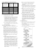
Figure 12: Gas Valve Pressure Tap D. Prepare to check operation. 1. Obtain gas heating value (in Btu per cubic foot) from gas supplier. 2. Connect manometer to pressure tap on gas valve. See Figure 12. 3. For natural gas fired boiler, temporarily turn off all other gas-fired appliances. E. Follow Operating Instructions to place boiler in operation. See Figure 17. F. Sequence of Operation. See Figure 14. If boiler fails to operate properly, see Troubleshooting Tree on pages 17-18. G.
Table 6: Gas Flow Rate in Cubic Feet per Hour Seconds for One Revolution Figure 16: Main Burner Flame J. Check thermostat operation. Raise and lower temperature setting to start and stop boiler operation. K. Check ignition control module shut-off. Disconnect igniter/sensor cable from Terminal 9 (SPARK). Gas valve should close and pilot and main burners should extinguish. L. Check low water cut-off (if used). Drain boiler water below LWCO set point. Burners should extinguish. M. Check limit. 1.
Figure 17: Operating Instructions Adjust gas valve pressure regulator as necessary (turn adjustment screw counterclockwise to decrease manifold pressure, or clockwise to increase manifold pressure). If pressure can not be attained, check gas valve inlet pressure. If less than minimum gas supply pressure listed on rating label, contact gas supplier for assistance. subsequent boiler operation. 2. Ventilate the boiler room, set the high limit to its maximum setting, set the thermostat to call for heat.
TROUBLE SHOOTING GUIDE SPLIT (SEPARATE) CONTROLS, 24 VOLT OPERATION WITH ELECTRONIC IGNITION AND INTERMITTENT CIRCULATION NOTE: 1. Read Sequence of Operation prior to using Trouble Shooting Guide. See Page 14. 2. Prior to replacing a control, always check for broken wires or loose connectors that provide power to that control.
Note: Minimum pilot signal should be 1.0 microamps. Disconnect Pilot Ground wire from Module and connect DC microammeter between Ground Terminal and Pilot Ground wire.
Important Product Safety Information Refractory Ceramic Fiber Product Warning: This product contains refractory ceramic fibers (RCF). RCF has been classified as a possible human carcinogen. After this product is fired, RCF may, when exposed to extremely high temperature (>1800F), change into a known human carcinogen. When disturbed as a result of servicing or repair, RCF becomes airborne and, if inhaled, may be hazardous to your health.
VIII. Service A. General. Inspection and service should be conducted a. If passageways are free of soot and obstruction, replace canopy, secure and seal using kit available from Burnham Distributors, Part No. 6111716. annually. Turn off electrical power and gas supply while conducting service or maintenance. Follow instructions TO TURN OFF GAS TO APPLIANCE. See Figure 17. b. If passageways need cleaning, remove burners as described in Paragraph F below.
Table 7: Pilot Burner Location Pilot Burner Located Between Main Boiler Model Main Burner with 60° Pilot Bracket * 203PV 1 1 & 2 204PV 2 2 & 3 205PV 3 3 & 4 206PV 4 4 & 5 Burners * * Main burners numbered left to right as viewed from front of boiler. at rear of burner. See Figure 11. Slide burner over orifice. 7. Reconnect pilot gas supply, igniter/sensor cable, and ground wire. Reinstall Burner Access Panel. Reconnect Flame Rollout Switch wires. Figure 18: Spark Gap Setting G.
Table 8: Minimum Suction Pressure Boiler Model Minimum Suction Pressure 203PV -0.50 inches w.c. 204PV -0.50 inches w.c. 205PV -0.80 inches w.c. 206PV -0.80 inches w.c. I. Lubrication. There are no parts requiring lubrication by service technician or owner. Circulator bearings are water lubricated. Blower motor bearings are factory sealed.
IX. Repair Parts All Series 2PV Repair Parts may be obtained through your local Burnham Wholesale distributor. Should you require assistance in locating a Burnham distributor in your area, or have questions regarding the availability of Burnham products or repair parts, please contact your Burnham Regional Sales Office as listed below. Burnham Corporation Regional Offices A . Burnham Corporation - Central & Western Regions C . P.O.
[Quantity] Part Number Key Description No. 203PV 1. Section Assembly 204PV 205PV 206PV 617170321 617170421 617170521 617170621 2. Canopy/Blower Assembly [1] 61117034 [1] 61117044 [1] 61117054 [1] 61117064 2A Canopy 2B Carriage Bolt, ¼-20 x 1" 2C Washer, ¼, SAE 2D Nut,¼-20, Heavy Hex 2E Blower Mounting Gasket [Included in Key No.
Key Description No. [Quantity] Part Number 203PV 204PV 205PV 206PV 3.
[Quantity] Part Number Key No. Description 203PV 204PV 205PV 206PV [2] 8236099 [4] 8236099 [6] 8236099 [8] 8236099 4.
Key No. [Quantity] Part Number Description 203PV 204PV 205PV 206PV 5. Pilot Burner and Gas Valve Pilot Assembly, Natural Gas, Honeywell Q348A1333 [1] 8236104 Pilot Assembly, LP Gas, Honeywell Q348A1341 [1] 8236107 5A Pilot Orifice, Natural Gas Honeywell 388146NE 5B Included with Key No.5A Pilot Orifice, LP/Propane Honeywell 388146KP 5C Compression Nut/Fitting, 1/8" OD x ¼ NPT 5D Pilot Tubing, 1/8" OD x 30" Included with Key No.
Key No. [Quantity] Part Number Description 203PV 204PV 205PV 206PV [1] 604170312 [1] 604170412 [1] 604170512 [1] 604170612 6.
[Quantity] Part Number Key No. Description 203PV 204PV 205PV 206PV 7.