INSTALLATION, OPERATING AND SERVICE INSTRUCTIONS FOR Series 2® Gas - Fired Boiler 9700609 9700609 F o r s e r vi c e o r r e p a i r s t o b o i le r, c a ll yo ur he a t i ng c o nt r a c t o r. W he n s e e k i ng i nf o r m a t i o n o n b o i le r, p r o vi d e B o i l e r M o d e l N u m b e r a n d S e r i a l N u m b e r a s s h o w n o n R a t i n g L a b e l .
NOTE: The equipment shall be installed in accordance with those installation regulations in force in the area where the installation is to be made. These shall be carefully followed in all cases. Authorities having jurisdiction shall be consulted before installations are made. All wiring on boilers installed in the USA shall be made in accordance with the National Electrical Code and/or local regulations.
WARNING This boiler requires regular maintenance and service to operate safely. Follow the instructions contained in this manual. Improper installation, adjustment, alteration, service or maintenance can cause property damage, personal injury or loss of life. Read and understand the entire manual before attempting installation, start-up operation, or service.
TABLE OF CONTENTS I. Product Description, Specifications and Dimensional Data...................... 4 II. Pre-Installation & Boiler Mounting ............................................................ 6 III. Gas Piping................................................................................................. 8 IV. Boiler Water Piping.................................................................................... 9 V. Venting............................................................
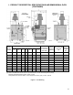
I. Product Description, Specifications and Dimensional Data (continued) Dimensions [Inches] Gas Approx. Water Recommended Connection Shipping Content Vent Size For Automatic Weight [gallons] [2] Gas Valve [lb.] Boiler Model Number A B C D E F G 202 18-3/4 10-3/4 6-3/8 4 45-5/8 8-1/2 10 [1] 1/2 2.5 3" dia. 212 202X 20 12 6 4 45-5/8 8-1/2 4-3/4 1/2 3.2 4” dia. 262 203 20 12 6 4 45-5/8 8-1/2 4-3/4 1/2 3.2 4” dia.
II. Pre-Installation and Boiler Mounting WARNING CAUTION If you do not follow these instructions exactly, a fire or explosion may result causing property damage or personal injury. Avoid operating this boiler in an environment where saw dust, loose insulation fibers, dry wall dust, etc. are present. If boiler is operated under these conditions, the burner interior and ports must be cleaned and inspected daily to insure proper operation. A. Inspect shipment carefully for any signs of damage.
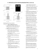
II. Pre-Installation and Boiler Mounting (continued) BOILER MODEL ‘W’ 202 10¾” (27.3cm) 202X 12” (30.5cm) 203 12” (30.5cm) 204 15¼” (38.7cm) 205 18½” (47.0cm) 206 21¾” (55.2cm) 207 25” (63.5cm) 208 28¼” (71.8cm) 209 31½” (80.0cm) 210 34¾” (88.3cm) Figure 2: Minimum Clearances a. CLOSET INSTALLATIONS (confined space) in a building of other than unusually tight construction (see definition below), provide combustion and ventilation air as shown in Figure 2. b.
III. Gas Piping A. Connect gas service from Meter to gas control The boiler must be isolated from the gas supply piping system by closing its individual manual shutoff valve during any pressure testing of the gas supply piping system at pressures equal to or less than ½ psig (3.5kPa). assembly in accordance with Local Piping Codes and requirements of Gas Company. They may require piping of larger size than Control Assembly Connection, especially if run from meter is long or includes several elbows.
IV. Boiler Water Piping A. BOILER water PIPING CAUTION Failure to properly pipe boiler may result in improper operation and damage to boiler or building. 1. Clearances - Hot water pipes do not require clearance from combustible construction. 2. Install drain valve and safety relief valve as shown in Figures 1 and 4. Note - Safety relief valve must be in vertical position. 3. Pipe safety relief valve discharge to floor.
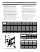
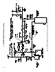
Figure 5: Recommended Water Piping for Zone Valve Zoned Heating Systems IV.
Figure 6: Recommended Water Piping for Circulator Zoned Heating Systems IV.
IV. Boiler Water Piping (continued) B. Optional Probe LWCO Installation WARNING DO NOT ATTEMPT to cut factory wires to install an aftermarket Low Water Cut Off (LWCO). Only use connections specifically identified for Low Water Cut Off. In all cases, follow the Low Water Cut Off (LWCO) manufacturer’s instructions. Figure 7: Recommended Piping for Combination Heating & Cooling (Refrigeration) Systems There are many possible causes of oxygen contamination such as: a.
IV. Boiler Water Piping (continued) 4. Piping and fittings required to install LWCO are field supplied. 5. When constructing a piping tree to install LWCO select fittings (tees, elbows etc) and nipples to have the same size (NPT) as boiler supply connection. At minimum, 1-1/4” tee with ¾” branch outlet is required to connect the probe LWCO to the supply piping. See Figure 8. DO NOT REDUCE THE SIZE OF NEAR BOILER SUPPLY FITTINGS AND NIPPLES. 6.
V. Venting A. INSTALL DRAFT HOOD without modification on outlet of flue collector (See Figure 1). Secure with sheet metal screws. WARNING Do not alter boiler draft hood or place any obstruction or non-approved damper in the breeching or vent system. Flue gas spillage can occur. ETL certification will become void. B. Install blocked vent switch The blocked vent switch assembly shipped taped to the top of the boiler includes a power cord and a switch attached to a mounting bracket.
V. Venting (continued) Figure 11: Plug-in Damper Installation 1. The vent damper must be the same size as the outlet of the Draft Hood supplied with the boiler (see Figure 1). Unpack the damper carefully - DO NOT FORCE IT CLOSED! Forcing the damper may damage the gear train and void the warranty. 2. Mount the vent damper assembly after the draft hood, as close to the draft hood as practicable without modification to the draft hood or vent damper.
V. Venting (continued) WARNING E. If an existing boiler is removed - Figure 12: Typical Vent Installation 6. Vent pipe to chimney must not be smaller than outlet on draft hood or damper. Although single wall vent pipe may be used, Type B is recommended. The venting system must be arranged so that only the boiler is served by the damper device. Installation per paragraph (C) complies with this provision. 7.
V. Venting (continued) Au moment du retrait d’une chaudière existante, les mesures suivantes doivent être prises pour chaque appareil toujours raccordé au système d’evacuation commun et qui fonctionne alors que d’autres appareils toujours raccordés au système d’évacuation ne fonctionnent pas: 1. Sceller toutes les ouvertures non utilisées du système d’évacuation. 2.
VI. Electrical A. Install a room thermostat on an inside wall about four feet above floor. Never install thermostat on an outside wall or where it will be influenced by drafts, hot or cold water pipes, lighting fixtures, television, rays of the sun or near a fireplace. Keep large furniture away from thermostat so there will be free movement of room air around this control. Heat Anticipator in Thermostat should be set to 0.6 amp.
VI.
VI.
VI.
VII. Start-up and Checkout A. Main burner check - Check main burners to see that they were not dislodged during shipment. Rear of burners should be in the slots in the rear of burner tray and the front of the burners should be seated completely on the orifices. B. Initial start 1. Fill entire heating system with water and vent air from system. Use the following procedure on a System equipped with zone valves. (See Figure 5). a. Close isolation valve in boiler supply piping. b.
VII.
VII. Start-up and Checkout (continued) C. CHECK GAS INPUT RATE TO BOILER NOTICE USA boilers built for installation at altitudes greater than 2,000 feet above sea level have been specially orificed to reduce gas input rate 4 percent per 1,000 feet above sea level per the National Fuel Gas Code, NFPA 54/ANSI Z223.1, Section 8.1.2 and Appendix F. Canadian boilers' orifice sizing is indicated on the rating label.
VII. Start-up and Checkout (continued) E. CHECK PILOT BURNER FLAME. See Figure 22. The pilot produces three (3) flames. The center flame should be steady, medium hard blue enveloping 3/8 to a ½ inch of sensing probe. F. Check thermostat operation. Raise and lower temperature setting as required to start and stop burners. G. Check high limit control. Jumper Thermostat connections in boiler wiring harness. Allow burners to operate until shutdown by limit. Remove jumper. H. CHECK DAMPER OPERATION.
VIII. Operation A. BOILER SEQUENCE OF OPERATION NORMAL OPERATION 1. The Series 2 Boilers are equipped with an Intelligent Hydronic Control (control). This control replaces the traditional separate ignition control, high limit switch and circulator relay and adds energy saving thermal purge features. Energy is saved by starting the circulator and delaying the burner start when there is residual heat available in the boiler. 2. The boiler’s sequence of operation is shown in Table 4. 3.
VIII. Operation (continued) The STA (status) display code has the below listed values. This list is also available on the control cover. Status Code Displayed in STA Mode Figure 24: Boiler Display The control display, along with Up ñ, Down ò, and “I” keys may be used to view boiler operating status (Figure 24). D. Viewing the Operating Mode Options In operating mode the user may view (but not change) boiler operating status, settings and troubleshooting information. To view control display information: 1.
VIII. Operation (continued) E. Changing the Adjustable Parameters To adjust parameters such as High Limit Setpoint and High Limit Differential: 1. Access the adjustment mode by pressing and holding the Up , Down , and “I” keys simultaneously for three (3) seconds. This procedure is intended to discourage unauthorized changes or accidental changes to limit settings. 2. Press the "I" key to display available Adjustment Mode options. Select an option.
VIII. Operation (continued) 7. Domestic Hot Water (DHW) Terminal Function () The control allows configuration of the DHW Circulator output functionality to help the Series 2 integrate into each installation more effectively. The DHW Circulator output can be connected to a domestic hot water circulator or a second heating zone circulator. These applications are selected as follows: a.
IX. Service and Maintenance A. Inspection should be conducted annually. Service as frequently as specified in paragraphs below. While service or maintenance is being done, Electrical Power and all Gas Supply to the Boiler must be "off". CAUTION Label all wires prior to disconnection when servicing controls. Wiring errors can cause improper and dangerous operation. Verify proper operation after servicing. ATTENTION. Au moment de l’entretien des commandes, étiquetez tous les fils avant de les débrancher.
IX. Service and Maintenance (continued) 1" Burner F. Removal or replacement of pilot assembly or pilot assembly parts If pilot assembly or pilot orifice spud need replacing, remove main burner with pilot using procedure described in paragraph (D). 40mm Burner Figure 26: Burner Cleaning and Installation i. Brush top of burners with a soft bristle brush, see Figure 26. Vacuum burners. Check orifices to see that drilled passageways are free of lint or dirt. j. Vacuum tip of Pilot Burner. 2.
Important Product Safety Information Refractory Ceramic Fiber Product Warning: The Repair Parts list designates parts that contain refractory ceramic fibers (RCF). RCF has been classified as a possible human carcinogen. When exposed to temperatures about 1805°F, such as during direct flame contact, RCF changes into crystalline silica, a known carcinogen. When disturbed as a result of servicing or repair, these substances become airborne and, if inhaled, may be hazardous to your health.
X. Troubleshooting A. Before troubleshooting The following pages contain trouble shooting tables for use in diagnosing control problems. When using these tables the following should be kept in mind: 1. This information is only meant to be used by a professional heating technician as an aid in diagnosing boiler problems. 2. Where applicable, follow all precautions outlined in the lighting instruction on page 23 . 3. In general, these tables assume that there are no loose or miswired electrical connections.
X. Troubleshooting (continued) B. Use Control Display (error) Number To Direct TroubleShooting Efforts If the control detects an error it will flash “” (error) followed by a number. Use this number to identify the boiler problem and corrective action in the table below.
X. Troubleshooting (continued) C. Use STA (status) Number To guide TroubleShooting The control will flash “” followed by a number. Use this number to identify the boiler problem in the table below: 1. Boiler and Circulator Off Display / Status Recommended Corrective Action The boiler has not detected a call for heat (tt = off and dh = off.
X. Troubleshooting (continued) 5. Circulator is On But Damper is Not Open Display / Status Recommended Corrective Action The control is waiting for the damper to open. Damper end switch has failed to close (end switch contact is stuck open). Combustion can never take place unless the damper blade is in the fully open position. Check the following: - During status “STA18" or “STA 20” the control terminal “P6 - 5” (yellow wire) is energized.
X. Troubleshooting (continued) 6. Circulator is On, Damper is Open But Boiler Fails to Start (continued) Display / Status Recommended Corrective Action 1. No Spark a. Can you hear sparking while is displayed? - If there is no spark noise replace the control. b.
XI. Repair Parts Section Assembly and Canopy Group.............................38 Base Assembly...................................................................40 Manifold and Main Burners 1 Inch Main Burners...................................................42 40mm Main Burners.........................................................44 Pilot Burner and Gas Valve..............................................46 Jacket Assembly................................................................47 Water Trim....
XI. Repair Parts (continued) Key No. Description Part No.
XI. Repair Parts (continued) Base Assembly Key Description No. Boiler Size Part No. Qty. 202 618600291 1 202X 618600391 1 203 618600391 1 204 618600491 1 205 618600591 1 206 618600691 1 207 618600791 1 208 618600891 1 209 618600991 1 210 618601091 1 202 718600291 1 202X 718600391 1 203 718600391 1 204 718600491 1 205 718600591 1 206 718600691 1 207 718600791 1 208 718600891 1 209 718600991 1 210 718601091 1 3.
XI. Repair Parts (continued) Key Description No. Boiler Size Part No. Qty. 3. Base Assembly Continued 3C Base Front Panel Assembly Burner Tray (1" Main Burners) 3D Burner Tray (40mm Main Burners) Key Description No. Boiler Size Part No. Qty. 3.
XI.
XI. Repair Parts (continued) Key Description No. Part No. Quantity 202 202X 203 204 205 206 207 208 209 210 4.
XI. Repair Parts (continued) Manifold and Main Burners (40mm Main Burners) Key No. Description Part No. Quantity 203 202X 204 205 206 207 208 209 210 1 1 2 3 4 5 6 7 8 1 1 1 1 1 1 1 1 1 4. 40 MM Main Burners Only 4A Main Burner 8236135 4B.
XI. Repair Parts (continued) Key Description No. Part No. Quantity 202X 203 204 205 206 207 208 209 210 4. 40 MM Main Burners Only (Continued) 4C.
XI. Repair Parts (continued) Key No. Description Part No. Quantity 202 202X 203 204 205 206 207 208 209 210 5. Pilot Burner and Gas Valve, Natural Gas 5A 5B 5C 5D 5E 5G 5H Pilot Burner, Honeywell Q3481B1206 with Fiberglass Insulated Integral 36" lg. Igniter/ Sensor Cable 103704-01 1 1 1 1 1 1 1 1 1 1 1 1 1 1 1 1 1 1 1 1 1 1 1 1 1 1 1 1 1 1 Pilot Burner Orifice, Honeywell NE22, 0.022" dia. Compression Fitting, 7/16" Hex x 5/8" lg.
XI. Repair Parts (continued) Key No. Description Part No. Quantity 202 202X 203 204 205 206 207 208 209 210 6.
Jacket Assembly XI.
XI. Repair Parts (continued) Key No. Description Part No. Quantity 202 202X 203 204 205 206 207 208 209 210 6.
XI.
XI. Repair Parts (continued) Key No. 7 Description Part No. Quantity Safety Relief Valve, 30 psi, 3/4 NPT, Conbraco 10-408-05 81660319 1 Safety Relief Valve, 50 psi, 3/4 NPT, Conbraco 10-303-10 101662-01 1 8056174 1 806602029 2 8. Circulator, Bell & Gossett SLC-30 Option 8A Circulator with Gaskets, Bell & Gossett NRF-22 8B Gasket, Bell & Gossett NRF-22 8.
XI. Repair Parts (continued) Controls Key No. Description Part No. Quantity 12.
XI. Repair Parts (continued) Draft Hood Key No. Description Part No.
Appendix A - Figures Figure Number Page Number Description Section I - Product Description, Specifications & Dimensional Data Figure 1 5 Line Drawing Section II - Pre-Installation & Boiler Mounting Figure 2 7 Minimum Clearances Section III - Gas Piping Figure 3 8 Recommended Gas Piping Section IV - Boiler Water Piping Figure 4 9 Near Boiler Piping Figure 5 10 Recommended Water Piping for Zone Valve Zoned Heating Systems Figure 6 11 Recommended Water Piping for Circulator Zoned Heating Sy
Appendix B - Tables Table Number Page Number Description Section III - Gas Piping Table 1 8 Maximum Capacity of Schedule 40 Pipe in CFH for Natural Gas Pressures of ½ psig or Less Table 2 8 Equivalent Length of Fittings Table 3 8 Specific Gravity Correction Factors for Natural Gas Section VIII - Operation Table 4 26 Sequence of Operation Table 5 26 Sequence Fail Table 6 28 Circulator Pre-purge Time example, (PP_ = 2 minutes) Table 7 29 DHW Terminal function (dh_) Selection = Domestic
U.S. Boiler Company, Inc. P.O. Box 3020 Lancaster, PA 17604 1-888-432-8887 www.usboiler.