
Install Instructions
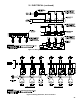


26
VIII. OPERATION
A. BOILER SEQUENCE OF OPERATION
NORMAL OPERATION
1. The Series 2 Boilers are equipped with an Intelligent
Hydronic Control (control). This control replaces
the traditional separate ignition control, high limit
switch and circulator relay and adds energy saving
thermal purge features. Energy is saved by starting
the circulator and delaying the burner start when
there is residual heat available in the boiler.
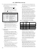
2. The boiler’s sequence of operation is shown in
Table 5.
3. When the thermostat calls for heat the control starts
the system circulator and the thermal purge
(circulator Pre-purge time) begins. If the time is
completed or boiler temperature is less than the Start
Temperature (140°F default) the start sequence
continues by energizing the vent damper. Once the
vent damper is fully open the ignition sequence is
started allowing gas ow and ignition of the burners.
Damper must be in open position when appliance
main burners are operating.
Le registre doit être ouvert lorsque le brûleur
principal de l'apareil fonctionne.
4. If the thermostat is not satised and the operating
setpoint is reached the system circulator will
continue to operate and the burners will stop. When
the boiler water temperature drops below the
setpoint less the differential setting the burners will
restart.
5. After the thermostat is satised the burners and
circulator are stopped and vent damper is closed.
6. When an indirect water heater aquastat call for heat
is wired to the DHW input, the control starts the
Domestic Hot Water circulator and, if the boiler
temperature is less than the operating setpoint less
differential, the vent damper is energized without
delay. Once the vent damper is fully open, the
ignition sequence is started allowing gas ow and
ignition of the burners.
B. BOILER FAULT
In the event the boiler fails to start, the control provides
status information to help determine the cause of the
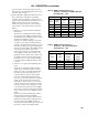
problem. Table 6 provides a list of boiler status codes
that are reported. Refer to the Troubleshooting Section
for more information.
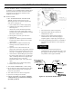
C. USING DISPLAY
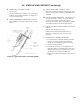
The control is located inside the boiler front door.
(Figure 23).
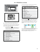
The control display, along with Up ñ, Down ò, and “I”
keys may be used to view boiler operating status (Figure 24).
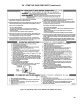
Status Codes displayed in STA Mode
Status STA Description
Standby
(Burner off
Circulator off)
1 No call for heat detected
Circulator
Pre-purge
(burner off
circulator on)
1
Either condition is true:
a. Call for heat detected and
boiler temperature higher
than operating setpoint.
b. Call for heat detected and
boiler temperature higher
than Start Temperature
(140°F default) and Circulator
Pre-purge Time has not
expired.
Self Test 17 Control internal checking
Drive Damper
Open
18
The damper is energized. The
control is waiting for the damper
switch to close. If the damper
end switch doesn't close within 60
seconds, the control goes to STA 20
Pre-purge 4
Damper is open for a 2 second
delay
Spark 6
The pilot fuel valve is open and
sparking is started.
Flame
Proving
7
The main fuel valve is open and
ame is being proven.
Running 8
The burner runs until the call for
heat is satised or the operating
setpoint is reached.
Table 5: Sequence of Operation
Status Codes displayed in STA Mode
Status STA Description
Retry /
Recycle
Delay
10
If the burner fails to light off (no
ame signal), it waits 5 minutes and
retries or if the control loses ame
signal during running, it will wait 10
seconds and then recycle.
Soft Lockout 13
System is shutdown and will restart
following a one hour enforced delay.
Hard Lockout 14
System is locked out. A manual or
power reset is required to be able to
light off again.
Limit Open 15
There is a call for heat from the
thermostat, but a Safety Limit is
open.
Flame
Present Out
of Sequence
16
Flame signal is still present when
expected to be 0 (no ame).
Damper
Failed to
Open
20
The damper is still energized and
the damper end switch has not
closed.
Table 6: Sequence Fault