
Install Instructions


32
1. TO REMOVE BURNERS FOR CLEANING,
CHANGING ORIFICE PLUGS, OR REPAIRS.
a. Remove the jacket front panel.
b. Disconnect pilot tubing at the gas valve. See
Figure 17.
c. Disconnect 3-wire plug at the gas valve.
d. 40mm burners only. Remove injection shield
assembly, where used. See Figure 26.
e. Remove wires to ame roll-out switch.
f. Remove the burner access panel.
g. Mark the location of the pilot main burner on the
manifold if the marking on manifold is missing
or obliterated.
h. Hold burner at throat. Lift front of burner to
clear orice. Burner which holds pilot can only
be removed by lifting the burner adjacent to its
right rst.
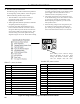
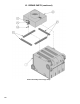
i. Brush top of burners with a soft bristle brush, see
Figure 26. Vacuum burners. Check orices to see
that drilled passageways are free of lint or dirt.
j. Vacuum tip of Pilot Burner.
2. CLEAN FIREBOX by vacuuming. Exercise care
not to disturb insulation inside the base.
3. INSTALL BURNERS by reversing procedure used
to remove burners. Make sure burner with pilot
assembly is in same location as original installation
- see Table 10.
Check burners to see that they are located properly
in slot at rear of burner tray, see Figure 26. Reinstall
injection shield assembly (40mm burners only,
where used) and burner access panel. Reconnect
ame roll-out switch wires, gas valve wires and
pilot lead.
4. CHECK MAIN BURNER and PILOT FLAMES,
see procedure in Section VII Start-up and Checkout,
paragraphs D and E.
E. CHECK ALL CONTROLS AND DAMPER
OPERATION ANNUALLY see procedure in Section
VII Start-up and Checkout, paragraphs F through I.
F. INSPECT LOW WATER CUTOFF (if used)
1. Clean and test probe-type per manufacturer's
instruction.
2. Flush oat-type weekly or as recommended by
manufacturer.
G. REMOVAL OR REPLACEMENT OF PILOT
ASSEMBLY OR PILOT ASSEMBLY PARTS
If pilot assembly or pilot orice spud need replacing,
remove main burner with pilot using procedure
described in paragraph (D).
1. To replace orice spud:
a. Disconnect pilot tubing. The Honeywell Q3481B
pilot orices are spud type retained by the
compression tting. Replace with desired orice
spud. See Key No. 5B in Repair Parts Section.
b. Reconnect pilot tubing and check for leaks.
2. To replace complete pilot assembly.
a. Remove machine screw holding pilot burner to
pilot bracket.
Figure 26: Burner Cleaning and Installation
1" Burner
40mm Burner
IX. SERVICE AND MAINTENANCE (continued)
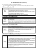
Table 10: Pilot Burner Location
Boiler
Model
Main Burner with
Pilot Bracket *
Pilot Burner Located
Between Main
Burners *
1 Inch 40mm 1 Inch 40mm
202 1 1 1 & 2 ---
202X 1 1 1 & 2 1 & 2
203 1 1 1 & 2 1 & 2
204 2 2 2 & 3 2 & 3
205 3 2 3 & 4 2 & 3
206 4 3 4 & 5 3 & 4
207 6 3 6 & 7 3 & 4
208 7 4 7 & 8 4 & 5
209 8 4 8 & 9 4 & 5
210 9 5 9 & 10 5 & 6
* Main burners numbered left to right as viewed from
front of boiler.