
Install Instructions


13
4. Piping and ttings required to install LWCO are
eld supplied.
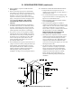
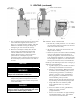
5. When constructing a piping tree to install LWCO
select ttings (tees, elbows etc) and nipples to have
the same size (NPT) as boiler supply connection. At
minimum, 1-1/4” tee with ¾” branch outlet is
required to connect the probe LWCO to the supply
piping. See Figure 8 for location and piping of the
LWCO. DO NOT REDUCE THE SIZE OF
NEAR BOILER SUPPLY FITTINGS AND
NIPPLES.
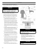
6. Installation of manual shutoff valve located above
the LWCO and the boiler is recommended to allow
servicing. Thus LWCO probe can be removed for
inspection without draining the heating system. An
annual inspection of the probe is recommended.
7. The presence of water covering properly installed
LWCO probe will cause the normally open contact
of the LWCO to close, thus providing continuity of
the 24 VAC service to the boiler gas valve. When
water level drops below probe, LWCO contact
opens up breaking 24V supply to gas valve and
preventing the boiler to re.
8. 2012 compliant Series 2 gas hot water boilers have a
“plug-in” provision in factory wiring that will accept
optional 24VAC probe LWCO harness connector.
The optional LWCO kit (P/N 104083-01) includes
24VAC probe LWCO, Harness and Instructions
addressing piping, wiring and testing after
installation. See Figure 13 for wiring of the LWCO.
IV. BOILER WATER PIPING (continued)
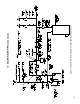
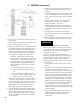
Figure 9: Recommended Auxiliary Limit Location
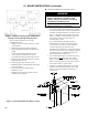
C. OPTIONAL AUXILIARY LIMIT INSTALLATION
1. Some jurisdictions may require the use of an
Auxiliary Limit control with a hot water boiler as a
redundant safety control.
2. The recommended location for an Auxiliary Limit
on gas hot water boilers is in the supply piping. See
Figure 9 for recommended location.
3. Piping and ttings required to install an Auxiliary
Limit are eld supplied.
4. When constructing a piping tree to install an
Auxiliary Limit select ttings (tees, elbows etc) and
nipples to have the same size (NPT) as boiler supply
connection. At minimum, 1-1/4” tee with 1/2”
branch outlet is required to install the limit well into
the supply piping. See Figure 9. DO NOT
REDUCE THE SIZE OF NEAR BOILER
SUPPLY FITTINGS AND NIPPLES.
5. When boiler water temperature reaches or exceeds
Auxiliary Limit setting, the limit normally closed
contact will open, thus interrupting the 24 VAC
service to the boiler gas valve. When boiler water
temperature drops below limit differential, limit
contact closes restoring 24V supply to gas valve and
allowing the boiler to re.
6. Gas hot water boilers equipped with Intelligent
Hydronic Control have a “plug-in” provision in
factory wiring that will accept optional 24VAC
Auxiliary Limit harness connector. The optional
Auxiliary Limit kit (P/N 103696-01) includes
24VAC Auxiliary Limit, Well, Harness and
Instructions addressing wiring and testing after
installation.