
Install Instructions


14
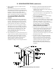
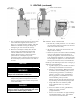
Figure 10: Blocked Vent Switch
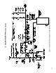
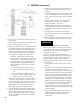
Installation Diagram
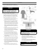
A. INSTALL DRAFT HOOD without modication on
outlet of ue collector (See Figure 1). Secure with sheet
metal screws.
WARNING
Do not alter boiler draft hood or place any
obstruction or non-approved damper in the
breeching or vent system. Flue gas spillage can
occur. ETL certication will become void.
B. INSTALL BLOCKED VENT SWITCH
The blocked vent switch assembly shipped taped to the
top of the boiler includes a power cord and a switch
attached to a mounting bracket. The mounting bracket
has a three tooth staggered comb stamping at one end
with a #10 sheet metal screw in the center tooth.
1. Untape the blocked vent switch assembly from the
top of the boiler and uncoil the power cord.
2. Blocked vent switch power cord (black and black
with white stripe wires) is attached to vent damper
harness with wire ties. The length of the cord is
sufcient to reach the blocked vent switch installed
at the left side of the draft hood skirt (see Figure 10).
However, if required, use at blade screwdriver to
dislodge black strain relief bushing, securing the
harness to boiler left side jacket, to adjust the length
as needed.
3. Position the mounting bracket (with switch attached)
onto the lower edge of the draft hood skirt by
locating the center tooth (with the #10 sheet metal
screw) on the outside and the other two teeth inside
the draft hood skirt. See Figure 10.
4. Slide the mounting bracket up tight against the
lower edge of the draft hood skirt, so that the #10
sheet metal screw is above the skirt's stiffening rib.
5. Secure the bracket in this position by tightening the
#10 sheet metal screw against the outer surface of
the draft hood skirt.
6. If required, reinsert the excess power cord through
the jacket side panel hole to take the slack out of the
wires running to up to the switch and vent damper.
7. Reposition the strain relief bushing around the
power cord at the jacket side panel, pinch the two
halves of the bushing together, and snap it back into
the hole in the jacket side panel to secure the power
cord to the jacket.
8. Be sure the power cord, mounting bracket, and
switch are secure and located as shown in Figure 10.
V. VENTING
WARNING
Failure to properly install and use this Blocked
Vent Switch may result in property damage,
personal injury or loss of life.
C. INSTALL VENT DAMPER
OPEN THE VENT DAMPER CARTON and remove
the Installation Instructions. READ THE
INSTALLATION INSTRUCTIONS THOROUGHLY
before proceeding.
The automatic gas control valve supplied on each
Series
2
®
boiler provides the redundancy referenced in
the vent damper Installation Instructions.
CAUTION
Do not use one vent damper to control two heating
appliances.