
Install Instructions


5
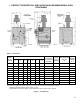
I. PRODUCT DESCRIPTION, SPECIFICATIONS AND DIMENSIONAL DATA
(CONTINUED)
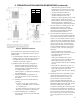
Figure 1: Line Drawing
Boiler
Model
Number
Dimensions [Inches] Gas
Connection
For Automatic
Gas Valve
Water
Content
[gallons]
Recommended
Vent Size
[2]
Approx.
Shipping
Weight
[lb.]
A B C D E F G
202 18-3/4 10-3/4 6-3/8 4 45-5/8 8-1/2 10 [1] 1/2 2.5 3" dia. 212
202X 20 12 6 4 45-5/8 8-1/2 4-3/4 1/2 3.2 4” dia. 262
203 20 12 6 4 45-5/8 8-1/2 4-3/4 1/2 3.2 4” dia. 262
204 23-1/4 15-1/4 7-5/8 5 47-1/8 9-1/8 4-3/4 1/2 4 5" dia. 306
205 26-1/2 18-1/2 9-1/4 6 48-1/2 9-3/4 5-1/4 1/2 4.7 6" dia. 354
206 29-3/4 21-3/4 10-7/8 6 48-1/2 9-3/4 5-1/4 1/2 5.5 6" dia. 414
207 33 25 12-1/2 7 50-1/8 10-3/8 6-5/8 3/4 6.2 7" dia. 458
208 36-1/4 28-1/4 14-1/8 7 50-1/8 10-3/8 6-5/8 3/4 7 7" dia. 514
209 39-1/2 31-1/2 15-3/4 8 52 11 7-1/4 3/4 7.7 8" dia. 550
210 42-3/4 34-3/4 17-3/8 8 52 11 7-1/4 3/4 8.5 8" dia. 608
[1] 202 only. Dimension 'G' includes allowance for 4" x 3" reducer furnished with boiler. See Figure 12.
[2] Refer to the National Fuel Gas Code for equivalent areas of circular and rectangular ue linings.
Maximum Allowable Working Pressure, Water - 50 PSI
Safety Relief Valve Pressure, Water - 30 PSI shipped from factory (std.); 50 PSI - optional
Table 1: Dimensions