
Install Instructions


9
A. BOILER WATER PIPING
CAUTION
Failure to properly pipe boiler may result in
improper operation and damage to boiler or
building.
1. CLEARANCES - Hot water pipes do not require
clearance from combustible construction.
2. Install drain valve and safety relief valve as shown
in Figures 1 and 4. Note - Safety relief valve must
be in vertical position.
3. Pipe safety relief valve discharge to oor.
WARNING
Safety relief valve discharge piping must be
piped near oor to eliminate potential of severe
burns. Do not pipe in any area where freezing
could occur. Do not install any shut-off valves.
4. Install Temperature and Pressure gauge externally in
boiler supply piping. All required components are
included at factory supplied Miscellaneous Parts
Bag (P/N 103669-01). See Figure 4 ‘Near Boiler
Piping’.
5. Install circulator with anges, gaskets and bolts and
circulator harness provided.
6. For recommended water piping, see Figures 5 and 6.
Also, consult Residential Hydronic Heating
Installation and Design I=B=R Guide.
7. If this boiler is used in connection with refrigeration
systems, the boiler must be installed so that the
chilled medium is piped in parallel with the heating
boiler using appropriate valves to prevent the chilled
medium from entering the boiler, see Figure 7. Also
consult Residential Hydronic Heating Installation
and Design I=B=R Guide.
If this Boiler is connected to heating coils located in
air handling units where they may be exposed to
refrigerated air, the boiler piping must be equipped
with ow control valves to prevent gravity
circulation of boiler water during the operation of
the cooling system.
8. Use a boiler bypass if the boiler is to be operated in
a system which has a large volume or excessive
radiation where low boiler water temperatures may
be encountered (i.e. converted gravity circulation
system, etc.).
Install a pipe tee at the boiler return along with a
second tee in the supply piping as shown in Figures
5 and 6. The bypass should be the same size as the
supply and return lines with valves located in the
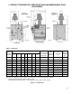
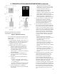
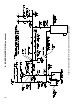
IV. BOILER WATER PIPING
Figure 4: Near Boiler Piping
bypass and supply outlet as illustrated in Figures 5
and 6 in order to regulate water ow to maintain
higher boiler water temperatures.
Set the boiler supply valve to fully open position,
and the boiler bypass valve to half throttle. Operate
the boiler and adjust the bypass valve to achieve
180°F to 200°F supply water temperature by closing
the bypass valve to decrease supply temperature or
opening the bypass valve to increase water
temperature. If the bypass valve is fully opened and
the boiler water temperature is still below 180°F,
slowly begin closing the boiler supply valve to
achieve 180°F to 200°F supply water temperature.
Caution: Never fully close the boiler supply valve.
10. If it is required to perform a long term pressure test
of the hydronic system, the boiler should rst be
isolated to avoid a pressure loss due to the escape of
air trapped in the boiler.
To perform a long term pressure test including the
boiler, ALL trapped air must rst be removed from
the boiler.
A loss of pressure during such a test, with no visible
water leakage, is an indication that the boiler
contained trapped air.
11. OXYGEN CORROSION:
Oxygen contamination of the boiler water will cause
corrosion of the iron and steel boiler components,
which can lead to failure. As such, any system must
be designed to prevent oxygen absorption in the rst
place or prevent it from reaching the boiler.
Problems caused by oxygen contamination of boiler
water are not covered by U.S. Boiler Company's
standard warranty.