Installation, Operating and Service Instructions for SERIES 2 ® Models: • Water Boiler • Cast Iron • Chimney Vent • Gas Fired • 202E • 203E • 204E • 205E • 206E • 207E • 208E • 209E Manual Contents Page Specifications . . . . . . . . . . . . . . . . . . . . . . . . . . 3 Pre-installation. . . . . . . . . . . . . . . . . . . . . . . . . . 4 Removing Existing Boiler. . . . . . . . . . . . . . . . . 5 Clearances. . . . . . . . . .
SERIES 2E Installation, Operating & Service Manual The City of New York requires a Licensed Master Plumber supervise the installation of this product. The Massachusetts Board of Plumbers and Gas Fitters has listed the Series 2E® Boiler. See the Massachusetts Board of Plumbers and Gas Fitters website, http://license.reg.state.ma.us/pubLic/pl_products/pb_product.asp for the latest Approval Code or ask your local Sales Representative.
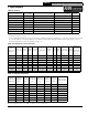
SERIES 2E Installation, Operating & Service Manual 1 Specifications Table 1A: Ratings Boiler Model Number Input1 (MBH) DOE Heating Capacity (MBH) AHRI Net Rating2 (MBH) AFUE 202E 38 32 28 84.0 203E 69 58 50 84.0 204E 103 87 76 84.0 205E 138 116 101 84.0 206E 172 145 126 84.0 207E 207 174 151 84.0 208E 241 202 176 84.0 209E 276 232 202 84.0 1 Input ratings can be used for elevations up to 2,000 ft.
SERIES 2E Installation, Operating & Service Manual 2 Pre-installation I. ! WARNING Carefully read all instructions before installing boiler. Failure to follow all instructions in proper order can cause personal injury or death. Provide combustion and ventilation air in accordance with the section "Air for Combustion and Ventilation," of the National Fuel Gas Code, ANSI Z223.1/NFPA 54, or applicable provisions of local building codes. ! WARNING A.
SERIES 2E Installation, Operating & Service Manual 3 Removing Existing Boiler A. If an Existing Boiler is Removed: When an existing boiler is removed from a common venting system, the common venting system is likely to be too large for proper venting of the appliances remaining connected to it.
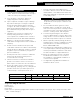
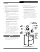
SERIES 2E Installation, Operating & Service Manual 4 Clearances (continued) Model A B 202E 6" 14" 203E 6" 14" 204E 6" 16" 205E 6" 19" 206E 6" 22" Figure 4-1: Minimum Closet Clearances Model A B 207E 8" 25" 208E 8" 28" 209E 8" 31" Figure 4-2: Minimum Alcove Clearances * Minimum radial clearance around draft hood and vent connector. ** Additional height required to maintain 6" clearance from all vent connector components.
SERIES 2E Installation, Operating & Service Manual 5 Venting A. Inspect chimney and remove any obstructions or restrictions. Clean chimney if previously used for solid or liquid fuel-burning appliances or fireplaces. B. Install vent system in accordance with "Venting of Appliances" of the National Fuel Gas Code, ANSI Z223.1/NFPA 54, or applicable provisions of local building codes. The Series 2E boiler is a Category I, draft hood equipped appliance with vent damper. D.
SERIES 2E Installation, Operating & Service Manual 5 Venting (continued) E. Install Vent Damper OPEN THE VENT CAMPER CARTON and remove Installation Instructions. READ INSTALLATION INSTRUCTIONS THOROUGHLY before proceeding. Automatic gas control valve supplied on each Series 2E boiler provides redundancy referenced in vent damper Installation Instructions. ! CAUTION Do not use one vent damper to control more than one heating appliance. 1.
SERIES 2E Installation, Operating & Service Manual 5 Venting (continued) G. Install vent termination (Masonry chimney and single wall metal pipe) 1. Termination shall extend at least 5 ft. in vertical height above highest connected appliance vent outlet. 2. Termination shall extend at least 3 ft. (2 ft. for single wall metal pipe) above roof penetration and at least 2 ft. above any portion of building within horizontal distance of 10 ft. H. Install vent termination: (Gas Vent) 1.
SERIES 2E Installation, Operating & Service Manual 6 Water Piping ! WARNING Failure to properly pipe boiler may result in improper operation and damage to boiler or building. A. Design and install boiler and system piping to prevent oxygen contamination of boiler water. Oxygen contamination sources are system leaks requiring addition of makeup water, fittings, and oxygen permeable materials in distribution system.
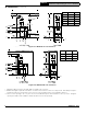
109443-01 - 6/19 System Circulator Optional Zone Valve Controlled System System Zone Valves To System Optional Circulator Zone Controlled System Zone Circulators Expansion Tank Backflow Preventer Cold Water Return IWH Return Indirect Water Heater (IWH) Full Port Isolation Valve Unions Full Port Isolation Valves Figure 6-2: Recommended Water Piping Direct Connection System Unions IWH Circulator Flow Check Full Port Isolation Valve IWH Supply Fill Valve Drain Valve Safety Relief Valve Pip
System Circulator Optional Zone Valve Controlled System System Zone Valves To System Optional Circulator Zone Controlled System Zone Circulators Flow Check To System Full Port Isolation Valves Expansion Tank Backflow Preventer Cold Water Return Fill Valve IWH Return Safety Relief Valve Pipe within 6" of floor or drain Drain Valve Full Port Isolation Valves Drain Valve Circulator Full Port Isolation Valves Indirect Water Heater (IWH) Full Port Isolation Valve Unions 'A' From Syste
SERIES 2E Installation, Operating & Service Manual 7 Gas Piping A. Size gas piping. Design system to provide adequate gas supply to boiler. Consider these factors: 1. Allowable pressure drop from point of delivery to boiler. Maximum allowable system pressure is ½ psig. Minimum gas valve inlet pressure is listed on rating label. See Table 7-1. Table 7-1: Gas Pressure Natural Gas Inlet Min (in. wc.) Inlet Max (in. wc.) Manifold (in. wc.) All Sizes 4.5 14.0 3.5 LP Inlet Min (in. wc.) Inlet Max (in.
SERIES 2E Installation, Operating & Service Manual 8 Electrical ! WARNING Electrical Shock Hazard. Wiring errors can cause improper or dangerous operation. Verify proper operation after installation. A. Install wiring so boiler is electrically bonded to ground in accordance with requirements of authority having jurisdiction, or in absence of such requirements, with the National Electrical Code, ANSI/NFPA 70. B. Install thermostat. Locate on inside wall approximately 4 feet above floor.
SERIES 2E Installation, Operating & Service Manual 8 Electrical (continued) Figure 8-1: Wiring Connection Diagram 109443-01 - 6/19 15
SERIES 2E Installation, Operating & Service Manual 8 Electrical (continued) Figure 8-2: Schematic Ladder Diagram 16 109443-01 - 6/19
SERIES 2E Installation, Operating & Service Manual 9 System Start-Up and Checkout A. Visual Main Burner Check Inspect burners for dislodgement during shipment. Rear of burners should be in vertical slots in rear of burner tray and front of burners should be seated completely on orifices. B. Initial LWCO Test Before filling boiler with water, turn on power to boiler and set thermostat to call for heat. Both the green "POWER" LED and amber "LOW WATER" LED should illuminate (see Figure 9-1).
SERIES 2E Installation, Operating & Service Manual 9 System Start-Up and Checkout (continued) Figure 9-2: Operating Instructions 18 109443-01 - 6/19
Installation, Operating & Service Manual SERIES 2E 9 System Start-Up and Checkout (continued) E. Perform gas leak test upstream of boiler shutoff valve. 3. Locate and address leaks using listed combustible gas detector,a non corrosive leak detection fluid or other listed leak detection method. 1. Protect boiler gas valve. a. For all testing over ½ psig, boiler and manual shutoff valve must be disconnected from gas supply piping. a.
Installation, Operating & Service Manual SERIES 2E 9 System Start-Up and Checkout (continued) J. Check Main Burner Flame (see Figure 9-6) valve can prevent pressure surge that blows out manometer fluid. 1. NORMAL FLAME: a. Clearly defined inner cone with no yellow tipping. b. Orange-yellow streaks caused by dust should not be confused with true yellow tipping. 2. ABNORMAL FLAME (if found, check inlet and outlet gas pressure. Procedure found in following steps): a.
SERIES 2E Installation, Operating & Service Manual 10 Operation A. Boiler Sequence of Operation (See Table 10-1) 1. When thermostat calls for heat, control starts system circulator. 2. If thermostat is satisfied with residual heat in boiler, or boiler water temperature is less than start temperature (140oF) setpoint, start sequence continues by energizing vent damper. Once vent damper is fully open, ignition sequence is started. Damper must be in open position when appliance main burners are operating. 3.
SERIES 2E Installation, Operating & Service Manual 10 Operation (continued) D. Viewing the Operating Mode Options Table: 10-4 In operating mode user may view (but not change) boiler operating status, settings and troubleshooting information. For example, when “I” key is pressed on control until “bt” is displayed, it will then flash three digit number (such as “180”) followed by “F” (or “C”). This indicates boiler water temperature is 180°F.
SERIES 2E Installation, Operating & Service Manual 10 Operation (continued) F. More Information About Adjustable Parameters 1. High Limit (HL_) Burner turns "off" when boiler water temperature (bt) is above this value. Operating setpoint (SP) equals high limit setpoint. 2. Differential (df_) Differential is number of degrees boiler temperature must decrease below the operating setpoint before boiler can restart. 3.
SERIES 2E Installation, Operating & Service Manual 10 Operation (continued) 7. Domestic Hot Water (DHW) Terminal Function () DHW Circulator output can be connected to a domestic hot water circulator or a second heating zone circulator. These applications are selected as follows: a. Indirect Water Heater (IWH) (dh_is set to Domestic Hot Water Demand (dh)) IWH limit is wired to "DHW" terminal on control. DHW circulator is wired to "DHW Circulator" on control wire harness.
SERIES 2E Installation, Operating & Service Manual 11 Before Leaving Jobsite Before Leaving Jobsite: Boiler and system filled with water Performed gas leak test Checked pilot burner flame Checked main burner flames Checked gas input rate Checked gas inlet pressure Checked gas manifold pressure Checked CO level in vent Checked vent damper operation Check ignition system safety shut-off device Tested LWCO functionality Tested high limit operation Tested add
SERIES 2E Installation, Operating & Service Manual 12 Service and Maintenance Important Product Safety Information: Refractory Ceramic Fiber Product WARNING Some boiler components use materials that contain refractory ceramic fibers (RCF). RCF has been classified as a possible human carcinogen. When exposed to elevated temperatures, RCF may change into crystalline silica, a known carcinogen.
SERIES 2E Installation, Operating & Service Manual 12 Service and Maintenance (continued) ! WARNING Service on this boiler should be undertaken only by trained and skilled personnel from a qualified service agency. Inspections should be performed at intervals specified in this manual. Maintain manual in a legible condition. • Keep boiler area clear and free of combustible materials, gasoline and other flammable vapors and liquids.
SERIES 2E Installation, Operating & Service Manual 12 Service and Maintenance (continued) D. Clean Main Burners and Firebox. 1. To remove burners for cleaning, changing orifices, or repairs: a. Remove Jacket Front Panel. b. Disconnect pilot tubing at gas valve. c. Disconnect 3-wire plug at the gas valve. d. Remove wires to flame roll-out switch. e. Disconnect ignitor sensor cable at boiler control. f. Remove the burner access panel. g.
SERIES 2E Installation, Operating & Service Manual 12 Service and Maintenance (continued) Q. Test Vent Damper Operation Vent damper must be in open position when main burners are operating. R. Test Functionality of LWCO See "Start-up and Checkout - Check LWCO Functionality. S. Check High Limit Control See " Start-up and Checkout - Check High Limit Control". T. Check Thermostat Operation See "Start-up and Checkout - Check Thermostat Operation" U. Check CO detector operation (if available). V. Lubrication.
SERIES 2E Installation, Operating & Service Manual 13 How It Works Series 2E boilers are equipped with an Intelligent Hydronic Control. This control combines features such as ignition control, high limit switch, and circulator relays. Energy is saved by using a thermal purge feature that starts the circulator and delays burner start when residual heat is available in boiler. When thermostat calls for heat, control module starts system circulator, checks safety limits, and activates vent damper.
SERIES 2E Installation, Operating & Service Manual 13 How It Works (continued) 9 3 4 2 5 1 7 8 6 109443-01 - 6/19 31
SERIES 2E Installation, Operating & Service Manual 14 Troubleshooting A. Before Troubleshooting When using troubleshooting tables, keep in mind: 1. Troubleshooting should be completed by a professional heating technician. 2. Before seeking technical assistance, the servicing technician should have a electrical meter and gas pressure gauge available for use. 3. Check electrical connections on boiler before proceeding (see Figure 8-1 and Figure 8-2). a.
SERIES 2E Installation, Operating & Service Manual 14 Troubleshooting (continued) C. Use Control Display (ERROR) Number to Direct Troubleshooting Efforts If control detects an error it will flash “” (error) followed by a number. Use this number to identify boiler problem and corrective action in table below.
SERIES 2E Installation, Operating & Service Manual 14 Troubleshooting (continued) D. Use STA (STATUS) Number to Guide Troubleshooting Control will flash “” followed by a number. Use this number to identify the boiler problem in table below: 1. Boiler and Circulator Off Display / Status Recommended Corrective Action Boiler has not detected a call for heat (tt = off and dh = off).
SERIES 2E Installation, Operating & Service Manual 14 Troubleshooting (continued) 5. Circulator is On But Damper is Not Open Display / Status Recommended Corrective Action Control is waiting for damper to open. Damper end switch has failed to close (end switch contact is stuck open). Combustion can never take place unless damper blade is in the fully open position. Check following: - During status “STA18" or “STA 20” control terminal “P6 - 5” (yellow wire) is energized.
SERIES 2E Installation, Operating & Service Manual 14 Troubleshooting (continued) 6. Circulator is On, Damper is Open But Boiler Fails to Start (continued) Display / Status Recommended Corrective Action 1. No Spark a. Can you hear sparking while is displayed? - If there is no spark noise replace control. b.
SERIES 2E Installation, Operating & Service Manual 15 Service Parts All Series 2E Service Parts may be obtained through your local U.S. Boiler Company Wholesale distributor. Should you require assistance in locating a U.S. Boiler Company Distributor in your area, or have questions regarding the availability of U.S. Boiler Company products or service parts, please contact U.S. Boiler Company Customer Service at (717) 481-8400 or Fax (717) 481-8408. 1C 1B 1A Key No.
SERIES 2E Installation, Operating & Service Manual 15 Service Parts (continued) Key No.
SERIES 2E Installation, Operating & Service Manual 15 Service Parts (continued) Key No.
SERIES 2E Installation, Operating & Service Manual 15 Service Parts (continued) Key No.
Installation, Operating & Service Manual SERIES 2E 15 Service Parts (continued) 5C 5A 5B 5E 5D Key No.
SERIES 2E Installation, Operating & Service Manual 15 Service Parts (continued) Key No.
SERIES 2E Installation, Operating & Service Manual 15 Service Parts (continued) 7A 7B Part Number [Quantity] Key No. Description 7A High Voltage Harness 109639-01 [1] 7B Low Voltage Harness 109640-01 [1] 202E 203E 204E 205E 206E 207E 208E 209E 207E 208E 209E Accessories: Part Number [Quantity] Key No.
SERIES 2E Appendix: Installation, Operating & Service Manual Combination Refrigeration/ Heating System A. If boiler is used in connection with refrigeration systems, boiler must be installed with chilled medium piped in parallel with the heating boiler using appropriate valves to prevent chilled medium from entering boiler. See Figure A-1. Also consult Residential Hydronic Heating Installation and Design I=B=R Guide. Supply main to combined heating & cooling system B.
SERIES 2E Appendix: Installation, Operating & Service Manual High Altitude Installations (above 2,000 ft.) Installations above 2,000 ft.
SERIES 2E Appendix: Installation, Operating & Service Manual Low Return Water Temperatures Thermal Shock: Cast iron boilers are very robust. 110°F and below return water temperatures will not cause thermal shock to U.S. Boiler castings. Condensation is a different matter: Cast iron boilers will tolerate intermittent periods of condensation but are not designed for extended condensation periods. Water temperatures below 120°F cause condensation that damage cast iron, burners and other components.
SERIES 2E Appendix: Installation, Operating & Service Manual Low Return Water Temperatures (continued) Primary-Secondary Pumping: This is an improvement over simple by-pass piping to reduce condensation. Again this is a fixed system. It can not adapt to variations in temperature and flow. Best Alternative: U.S. Boiler offers a system by-pass kit [part number 107795-01] that addresses these situations. A strap on temperature sensor measures boiler inlet temperatures.
SERIES 2E Appendix: Installation, Operating & Service Manual Wiring Schematics Wiring Schematic, Zone Valves Wiring Schematic, Zone Circulators 48 109443-01 - 6/19
SERIES 2E 109443-01 - 6/19 Installation, Operating & Service Manual 49
SERIES 2E 50 Installation, Operating & Service Manual 109443-01 - 6/19
SERIES 2E 109443-01 - 6/19 Installation, Operating & Service Manual 51
SERIES 2E Installation, Operating & Service Manual U.S. Boiler Company, Inc. P.O. Box 3020 Lancaster, PA 17604 1-888-432-8887 www.usboiler.