
User Guide


13
SERIES 2E
Installation, Operating & Service Manual
109443-01 - 6/19
A. Size gas piping. Design system to provide
adequate gas supply to boiler. Consider these
factors:
1. Allowable pressure drop from point of delivery
to boiler. Maximum allowable system pressure
is ½ psig. Minimum gas valve inlet pressure is
listed on rating label. See Table 7-1.
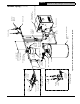
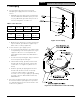
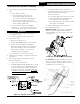
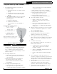
Figure 7-2: Gas Piping
7 Gas Piping
Natural
Gas
Inlet Min
(in. wc.)
Inlet Max
(in. wc.)
Manifold
(in. wc.)
All Sizes 4.5 14.0 3.5
LP
Inlet Min
(in. wc.)
Inlet Max
(in. wc.)
Manifold
(in. wc.)
All Sizes 11.0 14.0 10.0
Table 7-1: Gas Pressure
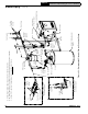
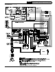
Figure 7-3: Gas Manifold and Control Assembly
2. Maximum gas demand. Consider existing and
expected future gas utilization equipment (i.e.
water heater, cooking equipment).
B. Connect boiler to gas supply system.
1. Use methods and materials in accordance with
local plumbing codes and requirements of gas
supplier. In absence of such requirements,
follow National Fuel Gas Code, ANSI Z223.1/
NFPA 54.
2. Use thread compounds (pipe dope) resistant to
action of liquefied petroleum gas.
3. Install sediment trap, ground-joint union and
manual shut-off valve upstream of boiler gas
control valve. See Figure 7-2 (within 6 ft. of
boiler).
4. All above ground gas piping upstream from
manual shut-off valve must be electrically
continuous and bonded to a grounding
electrode. Do not use gas piping as grounding
electrode. Refer to National Electrical Code,
ANSI/NFPA 70.
C. Pressure test. Boiler and its gas connection must
be leak tested before placing boiler in operation.
See Startup and Checkout Section E and H " Gas
Leak Test" for guidance.