
User Guide


20
SERIES 2E
Installation, Operating & Service Manual
109443-01 - 6/19
9 System Start-Up and Checkout (continued)
CAUTION
Avoid operating boiler in an environment where
saw dust, loose insulation fibers, dry wall dust,
etc. are present. If boiler is operated under
these conditions, burner interior and ports
must be cleaned and inspected daily to ensure
proper operation.
!
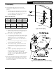
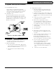
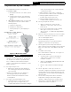
Figure 9-6: Main Burner Flame
J. Check Main Burner Flame (see Figure 9-6)
1. NORMAL FLAME:
a. Clearly defined inner cone with no yellow
tipping.
b. Orange-yellow streaks caused by dust
should not be confused with true yellow
tipping.
2. ABNORMAL FLAME (if found, check inlet and
outlet gas pressure. Procedure found in
following steps):
a. Overfired - large flame
b. Underfired - small flames
c. Lack of primary air - yellow tipping on
flames.
K. Check gas Inlet pressure
1. While boiler and all other gas appliances
are not firing, gas inlet pressure should not
exceed ½ psig.
2. While boiler and all other gas appliances
are firing, gas inlet pressure must be
between minimum and maximum shown
on rating label.
L. Check gas outlet (manifold) pressure
1. Install manometer on 1/8" outlet pressure
tap on gas valve (see Figure 9-3). Use
of shutoff valve between manometer and gas
valve can prevent pressure surge that blows
out manometer fluid.
2. Adjust regulator on gas valve so manifold
pressure matches values listed on rating label.
3. Turning regulator adjustment screw
clockwise () increases pressure.
4. Turning regulator adjustment screw
counterclockwise () decreases pressure.
M. Check gas input rate to boiler
1. When checking rate, ensure all other
appliances connected to same meter as
boiler are off.
2. Do not exceed input rate shown on rating
label (up to 2,000 ft.) For elevations
above 2,000 ft., see Appendix: High Altitude
Installations.
N. Measure carbon monoxide (CO) level in vent after
5 minutes of main burner operation. CO should
not exceed 400ppm air free.
O. Check vent damper operation.
Vent damper must be in open position when
appliance main burners are operating.
P. Check ignition system safety shut-off device.
After control has finished sparking, remove ignitor/
flame sense wire from control. Burners will shut
down.
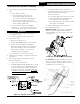
Q. Test LWCO functionality
Press "TEST" button on IDL 1200. See Figure 9-1.
Boiler should shut down.
• Set thermostat to call for heat and push
“TEST” button on IDL 1200 to simulate
low water condition.
• Amber “LOW WATER” LED will illuminate and
burner will shut down.
• Release “TEST” button and burner will light
off.
R. Check high limit control. (See Section 10
"Operation - High Limit" for details). Set thermostat
to higher than normal setpoint. Allow boiler to run
until high limit is achieved. (180F default) Burners
will shut down.
S. Check thermostat operation. Raise and lower
temperature setting to start and stop boiler
operation. Adjust thermostat to normal setting.
T. Review User's Information Manual and system
operation with owner or operator.