
User Guide


7
SERIES 2E
Installation, Operating & Service Manual
109443-01 - 6/19
5 Venting
A. Inspect chimney and remove any obstructions
or restric tions. Clean chimney if previously used
for solid or liquid fuel-burning appliances or
fireplaces.
B. Install vent system in accordance with "Venting
of Appliances" of the National Fuel Gas Code,
ANSI Z223.1/NFPA 54, or applicable provisions
of local building codes. The Series 2E boiler is a
Category I, draft hood equipped appliance with
vent damper.
1. Type B or Type L gas vent. Install in
accordance with manufacturer's installation
instructions.
2. Masonry or metal chimney. Build and install
in accordance with local building codes; or
local authority having jurisdiction; or Standard
for Chimneys, Fireplaces, Vents, and Solid
Fuel Burning Appliances, NFPA 211.
Masonry chimney must be lined with
listed clay flue lining or listed chimney
lining system.
3. Single wall metal vent. Allowed by ANSI
Z223.1/NFPA 54 under very restrictive
conditions.
4. Do not use CPVC, PVC, Polypropylene or
any other non-metallic vent pipe. Do not
use cellular core PVC (ASTM F891), cellular
core CPVC, or Radel
®
(polyphenolsulfone).
5. Do not cover non-metallic vent pipe and
fittings with thermal insulation.
C. Install Draft Hood without modification on outlet of
flue collector. Secure with sheet metal screws.
WARNING
Do not alter boiler draft hood or place any
obstruction or non listed damper in breeching
or vent system. Flue gas spillage and carbon
monoxide production can occur.
!
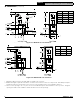
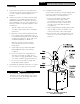
D. Install Blocked Vent Switch
The blocked vent switch assembly shipped taped
to the top of boiler includes a harness and a
switch attached to a mounting bracket.
1. Position mounting bracket (with switch
attached) onto lower edge of draft
hood skirt by locating center tooth (with
#10 sheet metal screw) on outside and
other two teeth inside draft hood skirt.
See Figure 5-1.
2. Slide mounting bracket up tight against lower
edge of draft hood skirt, so that #10 sheet
metal screw is above skirt's stiffening rib.
3. Be sure power cord, mounting bracket, and
switch are secure and located as shown in
Figure 5-1.
Figure 5-1 : Blocked Vent Switch
Installation Diagram