
Install Instructions


7
To Design Series-Loop Base-Ray
®
Installation –
1. Calculate the Heat Loss of each room using the procedure
outlined in the I=B=R Heat Loss Calculation Guide No.
H-21 or the ASHRAE Guide.
2. Using 210°F as design water temperature and 500 lbs/hr.
as ow rate, select length of BASE-RAY Assembly for
each room to produce desired output. (Design water
temperature other than 210°F may be used but should
not exceed 230°F.) If system designed on 20°F drop,
this 210°F average water temperature means roughly,
that under maximum load conditions, the water leaves
the boiler at 220°F and returns at 200°F and returns at
200°F. Since maximum load conditions occur only at
rare intervals, the system usually operates at considerably
lower water temperatures.
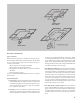
3. Locate BASE-RAY Assemblies on Floor Plan drawn to
scale.
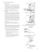
4. Layout Piping on Floor Plan as illustrated. Since the
temperature of the water decreases progressively from the
rst Heating Unit to the Last Heating Unit on a circuit, the
system should be laid out, if possible, so that the Heating
Units with the hotter water are in areas such as the living
room, bath and dining room. Heating Units in bedrooms,
kitchen and similar areas should be located on the end of
the loop.
5. Measure length of Circuit (horizontal and vertical)
from boiler supply to boiler return (include BASE-RAY
lengths). In Series Loop Systems, on rare instances a
BASE-RAY Assembly, Radiant Radiator or Slenderized
Radiator is connected to the main with branches. Since
a one-pipe tting is used, add 12 additional feet to the
measured length to obtain total length of Circuit.
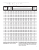
6. Knowing the load-length of the loop from Steps 2 and
5 above, Table A will indicate whether or not a standard
¾” or 1” circulator is adequate.
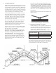
If, for a given output, the total length of the loop exceeds the
values shown in Table A, the loop may be split into two circuits
– see Illustration. Check load-length of each circuit.
Determine from Table B if 1” trunk is adequate.
For Piping Arrangements and Design conditions other than
those given above, follow procedure outlined in Residential
Hydronic Heating Installation and Design I=B=R Guide.
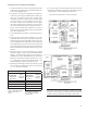
TABLE A TABLE B
Btu/Hr. Output
of BASE-RAY
Assemblies
Each Loop
Total
Length of
Loop Ft.
Btu/Hr. Output
of BASE-RAY
Assemblies All
Loops
Length of
Longest
Loop -Ft.
40,000 100 50,000 240
35,000 135 55,000 210
30,000 175 60,000 165
25,000 260 65,000 140
70,000 120
NOTE: Table based on 20°F
Drop through Circuit - ¾"
piping
NOTE: Table based on head
developed by Standard ¾"
or 1" circulator - 20°F Drop
through system.