
Install Instructions


8
Installation Details
A BASE-RAY
®
heating system is extremely easy to install – no
other heating system requires less labor. The same installa-
tion practices that are used in an ordinary radiator system are
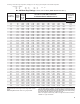
followed. Use conventional methods in selecting boiler and
pipe sizes, including mains, risers and branches. Supply and
return connections to BASE-RAY are made in the same way
as with conventional radiators.
Residential Hydronic Heating Installation and Design I=B=R
Guide shows installation details for both the conventional
piping system and the Series Loop System.
LOCATION OF BASE-RAY
BASE-RAY should be placed along exposed walls in place of
the regular wood baseboard. If the outside walls do not provide
sufcient space, place additional assemblies on inside wall.
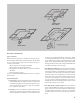
RECESSED
BASE-RAY may be recessed the depth of the lath and plaster,
and will extend into the room approximately one and a quarter
inches.
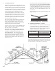
EXPANSION
BASE-RAY will expand about 1/8” in 10 lineal feet with a
temperature rise of 180°F. To provide for this, holes cut through
the oors should be larger than the pipe, and swing connections
should be located in branches between the Main and Risers.
VENTING
When two or more BASE-RAY assemblies are connected in
series on a hot water job it is necessary to vent each assembly,
unless the assemblies are connected at the top tapping. When
connected in series on a two-pipe steam job, the assemblies
should be connected at the bottom, and only one steam air
vent need be used.
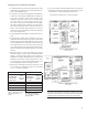
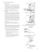
MAXIMUM DIMENSIONS OF FITTINGS
Inasmuch as the BASEBOARD EXTENSION PANELS and
PROJECTING CORNER PLATES are installed ush with
the face of BASE-RAY, there are a few types of ttings that
cannot be used in back of these parts because of the space
limitations. As shown in the adjacent diagram, the diameter
of the ttings cannot exceed 1½” – radiator union elbows and
regular pipe unions usually measure more, ¾” copper sweat
or screw ttings usually measure less. When iron pipe and t-
tings are used, straight connections may be made with ¾” right
and left coupling and corner connections with ¾” street elbow.
Because of these space limitations, U.S. Boiler Company has
available a No. 90-S Compression Connector for use with the
Projecting Corner Plate (see illustration).
Because of the radius on the face of INVERTED CORNER
PLATE, ttings having a diameter greater than 1½” may be
used (see illustration). For easy and quick connections at inside
corners, however, we recommend the U.S. Boiler Company No.
90-S Compression Connector for use with the 4-5/8” Inverted
Corner Plate. Both are illustrated.
VALVE ENCLOSURES have been designed to accommodate
almost all makes of shut-off valves and steam traps. See
Illustration for Enclosure dimensions.