
Alpine Installation, Operating, and Service Instructions


20
103448-10- 6/18
Table 4: Vent/Combustion Air Intake System Options
IV. Venting A. General Guidelines (continued)
Vent & Intake Materials Option
Penetration Through
Structure
Termination Figures
Component
Table
Reference
Section
Standard CPVC/PVC
Two-Pipe, CPVC/PVC
Vent and PVC Air Intake
1
Intake Horizontal Sidewall 90° Elbow w/ Screen
5, 6A, 6B 7A, 7B
A.B
Vent Horizontal Sidewall Coupling w/ Screen
2
Intake Horizontal Sidewall
Ipex Low Profile 6D, 6E 7D
Vent Horizontal Sidewall
3
Intake Horizontal Sidewall
Ipex FGV Concentric 6G, 6H, 6J 7F
Vent Horizontal Sidewall
4
Intake Horizontal Sidewall
DiversiTech (HVENT) 6D, 6F 7E
Vent Horizontal Sidewall
5
Intake Horizontal Sidewall
DiversiTech (CVENT)
Concentric
6G, 6H, 6J 7G
Vent Horizontal Sidewall
6
Intake Horizontal Sidewall 90° Elbow w/ Screen
6C 7A, 7B
Vent Vertical Roof Coupling w/ Screen
7
Intake Vertical Roof (2) 90° Elbows w/ Screen
7A, 8 7C
Vent Vertical Roof Coupling w/ Screen
8
Intake Vertical Roof
Ipex FGV Concentric 7B, 6H 7F
Vent Vertical Roof
9
Intake Vertical Roof
DiversiTech (CVENT)
Concentric
7C, 6H 7G
Vent Vertical Roof
Optional Polypropylene
Two-pipe, Rigid PP
Vent or Flexible PP
Vent (Vertical Only) and
Rigid PP or PVC Air
Intake
10
Intake Horizontal Sidewall
UV Resistant 90° Elbow
w/Screen
5, 6A, 6B
8, 9A, 9B,
9C, 9D
A, C
Vent Horizontal Sidewall
UV Resistant Straight Pipe
w/Screen
11
Intake Horizontal Sidewall
UV Resistant 90° Elbow
w/Screen
6C
Vent Vertical Roof
UV Resistant Straight Pipe
w/Screen
12
Intake Vertical Roof
(2) UV Resistant 90° Elbows
w/Screen
7A, 8
Vent Vertical Roof
UV Resistant Straight Pipe
w/Screen
13
Intake Horizontal Sidewall
UV Resistant 90° Elbow
w/Screen
16A, 16B
Vent Vertical Roof
Polypropylene Flex Terminal
(B-vent Chase
used for vent only)
14
Intake Vertical Roof
Polypropylene Flex Terminal
(B-vent Chase used for vent
and air intake)
16D, 16E
Vent Vertical Roof
Optional Stainless Steel
Two-pipe, SS Vent and
Galvanized Steel or
PVC
Air Intake
15
Intake Horizontal Sidewall 90° Elbow w/Screen
5, 6A, 6B
10A, 10B A, D
Vent Horizontal Sidewall
Straight Termination
w/Screen
16
Intake Horizontal Sidewall 90° Elbow w/Screen
6C
Vent Vertical Roof
Straight Termination
w/Screen
17
Intake Vertical Roof (2) 90° Elbows w/Screen
7A, 8
Vent Vertical Roof
Straight Termination
w/Screen
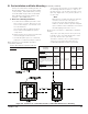
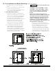
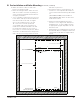
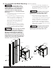
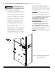
p. For multiple boiler installations with horizontal wall terminals, maintain minimum 12 in. (300 mm) horizontal
distance between adjacent boiler vent terminals. Maintaining greater spacing is recommended to avoid
frost damage to building surfaces where vent terminations are placed.
q. For multiple boiler installations with vertical roof terminals, maintain minimum 12 in. (300 mm) horizontal
distance between adjacent boiler vent terminals.