
Alpine Installation, Operating, and Service Instructions


103448-10 - 6/18 47
IV. Venting D. Stainless Steel Venting (continued)
a. Plan venting system to avoid possible
contact with plumbing or electrical wires.
Start at vent connector at boiler and work
towards vent termination.
b. Follow all manufacturer instructions and
warnings when preparing pipe ends for
joining and when assembling the vent/
combustion air system.
c. On horizontal pipe sections, orient all
welded seams at the 12:00 position. Do
not place longitudinal welded seams at the
bottom of horizontal sections of vent pipe.
d. Assemble the combustion air system using
either galvanized or PVC pipe.
i. If PVC piping is used, use PVC
cement to assemble the PVC intake
system components. See “B. CPVC/
PVC Venting” for combustion air pipe
installation instructions.
ii. If galvanized piping is used, use at least
two sheet metal screws per joint. Seal
outside of all joints
5. Horizontal Sidewall Vent Termination
a. Standard Two-Pipe Termination
See Figure 5.
i. Vent Termination
• Use a stainless steel coupling the
horizontal position.
4. System Assembly
• Apply a heavy bead of silicone to
the male end of the terminal before
inserting it into the last piece of pipe.
Orient the terminal so that the seam in
the terminal is at 12:00.
• Smooth the silicone over the seam
between the terminal and the last
piece of pipe, applying additional
silicone if necessary to ensure a tight
seal.
• Allow the silicone to cure per the
silicone manufacturer’s instructions
before operating the boiler.
ii. Combustion Air Termination
• Use an elbow in the downright
position. Elbow should protrude the
same distance from the wall as the
exhaust terminal as shown in Figure 5.
• Install a rodent screen (not supplied)
in the inlet terminal. Use a screen
having 1/2 in. x 1/2 in. (13 mm x 13
mm) mesh.
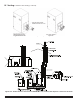
b. Optional Two-Pipe Snorkel Termination
See Figures 6A and 6B.
This installation will allow a maximum of
7 ft. (2.1 m) vertical exterior run of the vent/
combustion air piping to be installed on the
approved AL29-4C stainless steel horizontal
venting application.
i. Vent Termination
• After penetrating wall, install the
appropriate manufacturer’s 90° elbow
so that the elbow leg is in the up
direction.
• Install maximum vertical run of 7 ft.
(2.1 m) of appropriate manufacturer’s
vent pipe as shown in Figure 6A.
Asphyxiation Hazard. Vent systems made by Heat Fab, M&G / DuraVent and Z-Flex rely
on gaskets for proper sealing. When these vent systems are used, take the following precautions:
• Make sure that gasket is in position and undamaged in the female end of the pipe.
• Make sure that both the male and female pipes are free of damage prior to assembly.
• Only cut vent pipe as permitted by the vent manufacturer in accordance with their Instructions. When
pipe is cut, cut end must be square and carefully de-burred prior to
assembly.
WARNING
NOTICE The venting system must be free to expand and contract and supported in accordance with
installation instructions included by the original stainless steel venting component manufacturers, Heat
Fab, M&G / DuraVent or Z-Flex, whichever applicable.
NOTICE The joint between the terminal and
the last piece of pipe must be outside of the
building.
• Male end of terminal will fit into female
end of any of the listed stainless vent
systems.