
Alpine Installation, Operating, and Service Instructions


48
103448-10- 6/18
IV. Venting E. Removing the Existing Boiler
• At top of vent pipe length install
another appropriate manufacturer’s
90° elbow so that the elbow leg
is opposite the building’s exterior
surface.
• Install horizontal vent terminal
coupling.
• Brace exterior piping if required.
ii. Combustion Air Termination
• After penetrating wall, install a 90°
elbow so that the elbow leg is in the up
direction.
• Install maximum vertical run of 7 ft.
(2.1 m) of combustion air pipe as
shown in Figure 6B.
• At top of vent pipe length install
another 90° elbow so that the elbow
leg is opposite the building’s exterior
surface.
• Install rodent screen (not supplied)
and horizontal air terminal (elbow).
• Brace exterior piping if required.
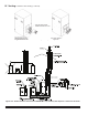
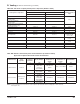
6. Vertical Vent Termination
a. Standard Two-Pipe Termination
See Figures 7 and 8.
i. Vent Termination
• Use the terminal supplied by the
vent system manufacturer shown in
Table 10B. Follow manufacturer’s
instructions to attach terminal to vent
system.
ii. Combustion Air Termination
• Install vertical combustion air terminal.
Vertical combustion air terminal
consists of a 180° bend (comprised
of two 90° elbows) as shown in Figure
7A.
• Install rodent screen (not supplied)
in the combustion air terminal. Use a
screen having 1/2 in. x 1/2 in. (13 mm
x 13 mm) or larger mesh.
7. Running Flexible Stainless Steel Vent (Liner)
Through Unused Chimney or Chase
a. Models ALP080B through ALP285B are
listed for vertical venting by installing
flexible stainless steel vent (M&G/
DuraVent FlexNSeal brand) in an UNUSED
masonry chimney/chase and supplying
combustion air through a separate wall or
roof combustion air terminal. The unused
chimney flue must be structurally sound and
in good repair.
b. Refer to Figure 17A for details of chimney
chase installation.
c. When flexible stainless steel pipe (liner)
is used for combustion product venting, it
must be installed at vertical or near vertical
plane. This will insure proper condensate
flow back towards the boiler.
d. Follow flexible stainless steel pipe
(liner) manufacturer specific installation
instructions regarding application/
listing, permits, minimum clearances to
combustibles, installation details (proper
joint assembly, pipe support and routing,
gasket and fitting installation, optional
tooling availability/usage, routing through
masonry combination of combustion
product venting and combustion air supply).
e. When there is a conflict between flexible
stainless steel pipe (liner) manufacturer
installation instructions and Alpine boiler
Installation, Operating and Service
Instructions, the more restrictive instructions
shall govern.
E. Removing the Existing Boiler
When an existing boiler is removed from a
common venting system, the common venting
system is likely to be too large for proper venting
of the remaining appliances. At the time of
removal of an existing boiler, the following steps
shall be followed with each appliance remaining
connected to the common venting system placed
in operation, while the other appliances remaining
connected to the common venting system are not
in operation.
1. Seal any unused openings in the common
venting system.
2. Visually inspect the venting system for proper
size and horizontal pitch and determine
there is no blockage or restriction, leakage,
corrosion, and other deficiencies which could
cause an unsafe condition.
3. Insofar as is practical, close all building doors
and windows and all doors between the space
in which the appliances remaining connected
to the common venting system are located and
other spaces of the building. Turn on clothes
dryers and any appliance not connected to the
common venting system. Turn on any exhaust
fans, such as range hoods and bathroom
exhausts, so they will operate at maxi mum
speed. Do not operate a summer exhaust fan.
Close fireplace dampers.
4. Place in operation the appliance being