
Alpine Installation, Operating, and Service Instructions


103448-10 - 6/18 91
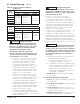
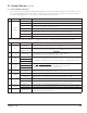
Boiler
Model
Altitude Range
0 - 7000 Ft.
% CO
2
% O
2
Range CO, PPM
ALP080B
9.9 - 8.2
(High Fire)
9.9 - 7.9
(Low Fire)
3.5 - 6.5
(High Fire)
3.5 - 7.0
(Low Fire)
Less than
100 PPM
ALP105B
ALP150B
ALP210B
ALP285B
Table 22: Typical Combustion Settings,
Natural Gas
IX. System Start-up (continued)
e. If low fire O
2
is too low (CO
2
is too high),
increase O
2
(decrease CO
2
) by turning offset
screw counterclockwise in less than 1/8 turn
increments and checking the O
2
(or CO
2
) after
each adjustment. If boiler is equipped with 2 gas
valves, offset screw adjustments must be done
to both gas valves equally and simultaneously.
Refer to Figure 37 for location of offset screw.
Verify CO is less than 100 ppm.
f. If low fire O
2
is too high (CO
2
is too low), decrease
O
2
(increase CO
2
) by turning offset screw
clockwise in less than 1/8 turn increments and
checking the O
2
(or CO
2
) after each adjustment. If
boiler is equipped with 2 gas valves, offset screw
adjustments must be done to both gas valves
equally and simultaneously. Refer to Figure 37 for
location of offset screw. Verify CO is less than 100
ppm.
3. Reinstall flue temperature sensor with sensor
cap into two-pipe vent adapter.
a. Inspect flue temperature sensor cap for
degradation. Replace if needed.
b. Use Molykote 111 grease to lubricate outer
surface of two-pipe vent adapter stub where
flue temperature sensor is inserted. Also
lubricate tip of flue temperature sensor.
Reinstall flue temperature sensor with cap
into two-pipe vent adapter.
4. Return boiler to normal operating mode by
pressing “Auto”.
M. Checking / Adjusting Gas Input Rate
1. Tu rn off gas supply to all appliances other than
gas-fired boiler.
2. Lock the boiler in high fire, following Step 2a
in Paragraph L.
3. Clock gas meter for at least 2 revolutions of
the dial, typically labeled ½ or 1 cubic foot per
revolution on the gas meter.
4. Determine gas flow rate in cubic feet per hour
based on elapsed time for 2 revolutions.
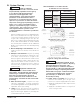
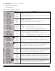
Boiler
Model
Altitude Range
0 - 7000 Ft.
% CO
2
% O
2
Range CO, PPM
ALP080B
11.4 - 9.5
(High Fire)
11.4 - 9.1
(Low Fire)
3.5 - 6.5
(High Fire)
3.5 - 7.0
(Low Fire)
Less than
100 PPM
ALP105B
ALP150B
ALP210B
ALP285B
Table 23: Typical Combustion Settings, LP Gas
b. If high fire O
2
is too low (CO
2
is too high),
increase O
2
(decrease CO
2
) by turning
the throttle screw clockwise in 1/4 turn
increments and checking the O
2
(or
CO
2
) after each adjustment. If boiler is
equipped with 2 gas valves, throttle screw
adjustments must be done to both gas
valves equally and simultaneously. Refer
to Figure 37 for location of throttle screw.
Verify CO is less than 100 ppm.
c. If high fire O
2
is too high (CO
2
is too low),
decrease O
2
(increase CO
2
) by turning
the throttle screw counter-clockwise in 1/4
turn increments and checking the O
2
(or
CO
2
) after each adjustment. If boiler is
equipped with 2 gas valves, throttle screw
adjustments must be done to both gas
valves equally and simultaneously. Refer
to Figure 37 for location of throttle screw.
Verify CO is less than 100 ppm.
d. Lock boiler in low fire and allow boiler to
operate for approximately 5 minutes before
taking combustion readings. Press “Low” to
lock boiler in low fire.
Make sure that all
adjustments at high fire are made with the
throttle, not the offset screw (see Figure 37).
The offset screw has been factory set using
precision instruments and must never be
adjusted in the field unnecessarily.
Attempting to adjust the offset screw
unnecessarily could result in damage to the
gas valve and may cause property damage,
personal injury or loss of life.
WARNING
Asphyxiation Hazard.
Offset screw is adjusted at the factory to the
specification. DO NOT touch the offset screw
if measured low fire O
2
(or CO
2
) is within limits
specified in Table 21 or 22.
WARNING
Asphyxiation Hazard. Install
flue temperature sensor and sensor cap into
two-pipe vent connector port upon completion
of combustion test. Failure to properly secure
the flue temperature sensor into the port could
lead to property damage, personal injury or
loss of life.
WARNING