
Alpine Installation, Operating, and Service Instructions


103448-10 - 6/18 93
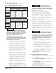
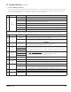
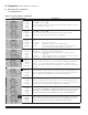
Table 24: Number of Clockwise Throttle
Screw Turns for LP Conversion
Boiler Model Gas Valve
Throttle Screw Turns at
Altitude Range
0 - 7000 Ft.
ALP080B
Dungs
GB-055
(½” NPT)
2¾
ALP105B 4
ALP150B 3¼
ALP210B 4
ALP285B
Dungs
GB-057
(¾” NPT)
4½
IX. System Start-up (continued)
with the installation instructions supplied with the
boiler. If an installed boiler is being converted,
connect the new gas supply to the boiler, check
for gas leaks, and purge the gas line up to the
boiler in accordance with the National Fuel Gas
Code, ANSI Z223.1/NFPA 54 and/or Natural
Gas and Propane Installation Code, CAN/CSA
B149.1 or the requirements of the authority having
jurisdiction.
3. Before attempting to start the boiler, make the
number of turns to the throttle screw called for in
Table 24.
4. Attempt to start the boiler using the Operating
Instructions located inside the lower front cover
of the boiler. If the boiler does not light on the
first try for ignition, allow to boiler to make at least
four more attempts to light. If boiler still does not
light, turn the throttle counter clockwise in 1/4
turn increments, allowing the boiler to make at
least three tries for ignition at each setting, until
the boiler lights.
5. After the burner lights, complete all steps
outlined in Paragraph L “Perform Combustion
Test” and Paragraph M “Checking/Adjusting Gas
Input Rate” before proceeding.
6. Verify that the gas inlet pressure is between
the upper and lower limits shown in Table 20 on
page 72 with all gas appliances (including the
converted boiler) both on and off.
7. A label sheet is provided with the boiler for
conversions from natural gas to LP gas. Once
conversion is completed, apply labels as follows:
a. Apply the “Rating Plate Label” adjacent to the
rating plate.
b. Apply the “Gas Valve Label” to a conspicuous
area on the gas valve.
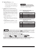
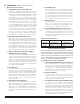
Figure 37: Dungs Gas Valve Detail
Asphyxiation Hazard. The
throttle adjustments shown in Table 24 are
approximate. The final throttle setting must be
found using a combustion analyzer. Leaving
the boiler in operation with a CO level in
excess of the value shown in Table 23 could
result in injury or death from carbon monoxide
poisoning.
Asphyxiation Hazard. These
instructions include a procedure for adjusting
the air-fuel mixture on this boiler. This
procedure requires a combustion analyzer to
measure the O
2
(or CO
2
) and Carbon Monoxide
(CO) levels in flue gas. Adjusting the air-fuel
mixture without a proper combustion analyzer
could result in unreliable boiler operation,
personal injury, or death due to carbon
monoxide poisoning.
Explosion Hazard.
Asphyxiation Hazard. This conversion should
be performed by a qualified service agency
in accordance with the manufacturer’s
instructions and all applicable codes
and requirements of the authority having
jurisdiction. If the information in these
instructions is not followed exactly, a fire, an
explosion or production of carbon monoxide
may result causing property damage, personal
injury, or loss of life. The qualified service
agency is responsible for proper conversion
of these boilers. The conversion is not proper
and complete until the operation of the
converted appliance is checked as specified in
this manual.
WARNING
WARNING
WARNING