
Alpine Installation, Operating, and Service Instructions


98
103448-10- 6/18
X. Operation C. Boiler Protection Features
Table 27: Frost Protection
C. Boiler Protection Features
1. Supply Water Temperature High Limit
The boiler is equipped with independent automatic
reset and a manual reset high limit devices. A supply
manifold mounted limit device provides the automatic
reset high limit. The automatic high limit is set to
200°F (93.3°C). The control monitors a supply water
temperature sensor that is also mounted in the supply
water manifold and an internal, manual reset high limit
If the temperature exceeds 210°F (98.9°C), a manual
reset hard lockout results. If the boiler is responding to
the internal Multiple Boiler Control Sequencer, Header
Sensor or, an External EMS demand, and the supply
water temperature increases above 190° F (87.7° C),
the control begins to reduce the blower maximum
speed setting and the temperature increases to 200°
F (93.3° C), a forced recycle results. Additionally, if
the supply temperature rises faster than the degrees
Fahrenheit per second limit, a soft lockout is activated.
2. High Differential Temperature Limit
The Control monitors the temperature difference
between the return and supply sensors. If this difference
exceeds 43°F (23.9°C), the control begins to reduce
the maximum blower speed. If temperature difference
exceeds 53°F (29.4°C), a forced boiler recycle results.
If the temperature difference exceeds 63°F (35°C),
the control will shut the unit down. The unit will restart
automatically once the temperature difference has
decreased and the minimum off time has expired.
3. Return Temperature Higher Than Supply
Temperature (Inversion Limit)
The Control monitors the supply and return temperature
sensors. If the return water temperature exceeds the
supply water temperature for longer than a limit time
delay, the Control shuts down the boiler and delays
restart. If the inverted temperature is detected more
than five times, the boiler manual reset Hard Lockout is
set. This condition is the result of incorrectly attaching
the supply and return piping.
4. External Limit
An external limit control can be installed between
terminals 11 and 12 on the low voltage terminal strip.
Be sure to remove the jumper when adding an external
limit control to the system. If the external limit opens,
the boiler will shut down and an open limit indication
and error code are provided. If the limit installed is a
manual reset type, it will need to be reset before the
boiler will operate.
5. Boiler Mounted Limit Devices
The Control monitors individual limit devices: pressure
switch, high limit device, condensate level switch,
Thermal Link (ALP285B only), Burner Door Thermostat
with manual reset (ALP285B only) and external limit
(optional). If any of these limits open, the boiler will
shut down and an individual open limit indication is
provided.
6. Stack High Limit
The Control monitors the flue gas temperature sensor
located in the vent connector. If the flue temperature
exceeds 184°F (84.4°C), the control begins to reduce
the maximum blower speed. If the flue temperature
exceeds 194°F (90.0°C), a forced boiler recycle results.
If the flue temperature exceeds 204°F (95.6°C), the
control activates a manual reset Hard Lockout.
7. Ignition Failure
The Control monitors ignition using a burner mounted
flame sensor. In the event of an ignition failure, the
control retries (ALP080B through ALP285B) 5 times
and then goes into soft lockout for one hour.
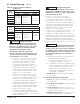
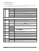
8. Central Heating System Frost Protection
When enabled, Frost Protection starts the boiler and
system pump and fires the boiler when low outside air
and low supply water temperatures are sensed. The
Control provides the following control action when frost
protection is enabled:
Device
Started
Start
Temperatures
Stop
Temperatures
Boiler & System
Pump
Outside Air < -22°F (-30°C)
Supply Water < 45°F (7.2°C)
Outside Air > -18°F (-28°C)
Supply Water > 50°F (10°C)
Boiler Supply Water < 38°F (3.3°C) Supply Water > 50°F (10°C)
FROST PROTECTION NOTE
The Control helps provide freeze protection for the boiler
water. Boiler flue gas condensate drain is not protected
from freezing. Since the Control only controls the system
and boiler circulators individual zones are not protected.
It is recommended that the boiler be installed in a location
that is not exposed to freezing temperatures.
D. Multiple Boiler Control Sequencer
1. “Plug & Play” Multiple Boiler Control Sequencer
When multiple boilers are installed, the Control’s
Sequencer may be used to coordinate and optimize
the operation of up to eight (8) boilers. Boilers are
connected into a “network” by simply “plugging in”
standard ethernet cables into each boiler’s “Boiler-To-
Boiler Communication” RJ45 connection.
2. Sequencer Master
A single Control is parameter selected to be the
Sequencer Master. The call for heat, outdoor and
header sensors, and common pumps are wired to the
Sequencer Master “enabled” Control.
3. Lead/Slave Sequencing & Equalized Run Time
One boiler is a “Lead” boiler and the remaining
networked boilers are “Slaves”. When demand is
increasing, the Lead boiler is the first to start and the
Slave boilers are started in sequential order (1,2,3,…)
until the demand is satisfied. When demand is
decreasing, the boilers are stopped in reverse order
with the Lead boiler stopped last (…,3,2,1). To equalize
the run time the sequencer automatically rotates the
Lead boiler after 24 hours of run time.