INSTALLATION, OPERATING AND SERVICE INSTRUCTIONS FOR ALPINE™ CONDENSING HIGH EFFICIENCY DIRECT VENT GAS - FIRED HOT WATER BOILER Size Range - 80 MBH through 285 MBH 9700609 TO THE INSTALLER: Affix these instructions adjacent to boiler. TO THE CONSUMER: Retain these instructions for future reference. As an ENERGY STAR® Partner, U.S.
IMPORTANT INFORMATION - READ CAREFULLY NOTE: The equipment shall be installed in accordance with those installation regulations enforced in the area where the installation is to be made. These regulations shall be carefully followed in all cases. Authorities having jurisdiction shall be consulted before installations are made. All wiring on boilers installed in the USA shall be made in accordance with the National Electrical Code and/or local regulations.
Special Installation Requirements for Massachusetts A. For all sidewall horizontally vented gas fueled equipment installed in every dwelling, building or structure used in whole or in part for residential purposes and where the sidewall exhaust vent termination is less than seven (7) feet above grade, the following requirements shall be satisfied: 1.
TABLE OF CONTENTS I. Product Description, Specifications and Dimensional Data...................... 5 II. Unpacking Boiler........................................................................................ 9 III. Pre-Installation and Boiler Mounting ........................................................ 10 IV. Venting...................................................................................................... 17 A. General Guidelines...............................................
I. Product Description, Specifications and Dimensional Data Alpine™ Series boilers are condensing high efficiency gas-fired direct vent hot water heating boilers designed for use in forced hot water space or space heating with indirect domestic hot water heating systems, where supply water temperature does not exceed 210°F.
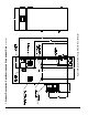
103448-08- 9/16 Figure 1A: Models ALP080B through ALP210B (Floor Mounted) I.
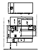
103448-08 - 9/16 7 Figure 1B: Models ALP080B through ALP210B (Wall or Floor Mounted) I.
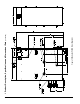
103448-08- 9/16 Figure 1C: Model ALP285B (Floor Mounted) I.
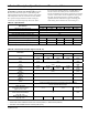
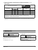
I. Product Description, Specifications and Dimensional Data (continued) Table 2: Ratings Alpine Series Gas-Fired Boilers Input (MBH) Model Number Min. Max. Heating Capacity (MBH) Net AHRI Ratings Water 1 (MBH) AFUE (%) ALP080B 16 80 72 63 95.0 ALP105B 21 105 96 83 95.0 ALP150B 30 150 136 118 95.0 ALP210B 42 210 194 169 95.0 ALP285B 57 285 262 228 95.0 Ratings shown are for installations at sea level and elevations up to 2000 ft. For elevations above 2000 ft.
III. Pre-Installation and Boiler Mounting WARNING Explosion Hazard. Asphyxiation Hazard. Electrical Shock Hazard. Installation of this boiler should be undertaken only by trained and skilled personnel from a qualified service agency. Follow these instructions exactly. Improper installation, adjustment, service, or maintenance can cause property damage, personal injury or loss of life.
III. Pre-Installation and Boiler Mounting G. General (continued) 2. Alpine boilers are not intended to support Floor must be able to support weight of boiler, water and all additional system components. b. Boiler must be level to prevent condensate from backing up inside the boiler. c. Provide adequate space for condensate piping or a condensate pump if required. external piping and venting. All external piping and venting must be supported independently of the boiler. 3.
III. Pre-Installation and Boiler Mounting G. General (continued) Boiler Service Clearances – Applicable to all Boiler Models: Top = 24 in. (610 mm), Front = 24 in. (610 mm), Left Side = 24 in. (610 mm), Right Side = 24 in. (610 mm), Rear = 24 in. (610 mm) The above clearances are recommended for service access but may be reduced to the Combustible Material Clearances provided: a. The boiler front is accessible through a door. b. Access is provided to the condensate trap located on the left side of boiler.
III. Pre-Installation and Boiler Mounting G. General (continued) c. 5/16 in. x 2 in. lag screws and 5/16 in. plated washers are intended for mounting the boiler directly onto studs covered with ½ in. drywall. When the boiler is attached to other types of construction, such as masonry, use fasteners capable of supporting the weight of the boiler and attached piping in accordance with good construction practice and applicable local codes. d. Make sure that the surface to which the boiler is mounted is plumb.
III. Pre-Installation and Boiler Mounting G. General (continued) CAUTION The outer edges of the template represent minimum side, top and bottom clearances to combustible material. If the template needs to be cut to fit into a selected location, it would indicate the minimum clearances to combustible material are not met. h. Attach the wall hanging bracket using the 5/16 in. x 2 in. lag screws and 5/16 in. plated washers, or other suitable anchors as appropriate (Figure 2D). Make sure the bracket is level.
III. Pre-Installation and Boiler Mounting G. General (continued) Figure 2E: Access Panel and Gasket Installation WARNING Access Panel must be installed while boiler is in operation. H. Boiler Stacking 1.
III. Pre-Installation and Boiler Mounting H. Boiler Stacking (continued) WARNING Asphyxiation Hazard. No common manifold venting is permitted. Each boiler must have its own individual vent and combustion air pipes and terminals. For side-wall venting individual model vent terminals must terminate not closer than 12 inches horizontally and three (3) feet vertically from each other in order to prevent combustion air contamination.
IV. Venting WARNING Asphyxiation Hazard. Failure to vent this boiler in accordance with these instructions could cause products of combustion to enter the building resulting in severe property damage, personal injury or death. Do not use a barometric damper, draft hood or vent damper with this boiler. Do not locate vent termination under a deck. Do not locate vent termination where exposed to prevailing winds.
IV. Venting A. General Guidelines (continued) A. General Guidelines 1. Listed Vent/Combustion Air Systems a. Install vent system in accordance with “Venting of Equipment” of the National Fuel Gas Code, ANSI Z223.1/NFPA 54 or “Venting Systems and Air Supply for Appliances” of the Natural Gas and Propane Installation Code, CAN/ CSA B149.1, or applicable provisions of local building codes. Contact local building or fire officials about restrictions and installation inspection in your area. b.
IV. Venting A. General Guidelines (continued) b. c. d. e. f. ii. Vertical Roof Venting: Use straight coupling on vent and two 90° elbows turned downwards for combustion air as shown in Figure 7A. and Figure 8). iii. For Alpine boilers factory build prior to January 2016, US Boiler provided PVC tees (3” or 4” as applicable to specific boiler model) to be used either as vent or air intake terminals.
IV. Venting A.
IV. Venting A. General Guidelines (continued) Table 5A: Vent and Combustion Air Pipe Sizes and Equivalent Lengths (Applies to All Listed Vent/Combustion Air System Options) Boiler Model Combustion Air Length Option Vent Length Pipe Dia., in. (mm) Min., ft. (m) Max., ft. (m) Pipe Dia., in. (mm) Min., ft. (m) Max., ft. (m) Reduced Diameter 2 (60) 2.5 (0.76) 60 (18.3) 2 (60) 2.5 (0.76) 60 (18.3) Factory Build 3 (80) 2.5 (0.76) 135 (41.1) 3 (80) 2.5 (0.76 135 (41.
IV. Venting B. CPVC/PVC Venting Table 6: Vent/Combustion Air Equivalent Length Calculation Work Sheet Combustion Air Component Equivalent Length Per Piece X Quantity = Vent Equivalent Subtotal Length X Equivalent Length Per Piece Quantity = Subtotal Equivalent Length Straight Pipe X = A E 90° Elbow, Short Radius X = B F 90° Elbow, Long Sweep/ Sanitary X = C G 45° Elbow X Combustion Air Total Equivalent Length = D = A+B+C+D H Vent Total Equivalent Length = E+F+G+H Notes: 1.
IV. Venting B.
IV. Venting B.
IV. Venting B.
IV. Venting B.
IV. Venting B. CPVC/PVC Venting (continued) Extend vent/combustion air piping to maintain minimum vertical (‘X’) and minimum horizontal (‘Y’) distance of 12 in. (300 mm) [18 in. (460 mm) Canada] from roof surface. Allow additional vertical (‘X’) distance for expected snow accumulation.
IV. Venting B. CPVC/PVC Venting (continued) Table 6A: Expansion Loop Lengths Nominal Pipe Dia. (In.) 2 3 Figure 10B: Field Installation of CPVC Vent Pipe Wall Mounted Boiler Builds 4 Length of Straight Run (Ft.) 20 30 40 50 60 20 30 40 50 60 20 30 40 50 60 Loop Length “L” (In.
IV. Venting B.
IV. Venting B.
IV. Venting B. CPVC/PVC Venting (continued) 1. Components 3. Near-Boiler Vent/Combustion Air Piping a. See Table 7A for CPVC/PVC vent and combustion air components included with boiler. b. See Table 7B for CPVC/PVC installer provided vent and combustion air components required for optional horizontal snorkel terminals shown in Figure 6B. c. See Table 7C for CPVC/PVC installer provided vent and combustion air components required for optional vertical roof terminals shown in Figures 7A and 8. d.
IV. Venting B. CPVC/PVC Venting (continued) d. Secure the pipe by tightening the metal strap worm screw. WARNING Failure to properly secure the vent into the elbow with the clamp could lead to property damage, personal injury or loss of life. e. The CPVC 30 in. long straight pipe may be cut to accommodate desired vent configuration. If the CPVC 30 in. straight pipe needs to be cut into two pieces to accommodate desired vent configuration, insure that the first vertical piece has minimum length of 12 in.
IV. Venting B. CPVC/PVC Venting (continued) Figure 12: Wall Penetration Clearances for PVC Vent Pipe 1. The wall penetration is 66 in. (1680 mm) or more, measured along the vent from the end of the CPVC pipe at the boiler vent connection to the wall. 2. The wall is 12 in. (300 mm) thick or less. 3. The minimum air space shown in Figure 12 is maintained around the outside of the vent pipe to provide air circulation.
IV. Venting B. CPVC/PVC Venting (continued) • Brace exterior piping if required. c. Optional Two-Pipe Termination into IPEX Low Profile or DiversiTech HVENT Terminal – horizontal thru sidewall, see Figures 6D and 6F. i. Vent Piping • Install fire stops where vent passes through framed walls. The fire stop must close the opening between the vent pipe and the structure. • Follow IPEX Low Profile or DiversiTech HVENT terminal instructions for installation details. ii.
IV. Venting C. Polypropylene Venting C. Polypropylene Venting WARNING Asphyxiation Hazard. Follow these instructions and the installation instructions included by the listed polypropylene venting component manufacturers, whichever applicable. Failure to do so could cause products of combustion to enter the building, resulting in severe property damage, personal injury or death.
IV. Venting C.
IV. Venting C.
IV. Venting C.
103448-08 - 9/16 39 4” 3” 2” Nominal Pipe Diameter NA 3PPS-ADL 2PPS-ADL 4PPS-04PVCM-4PPF 3PPS-03PVCM-3PPF 3PPS-03PVCM-2PPF PPS-PACL (810004128) 4PPS-LB2 3PPS-LB2 2PPS-LB2 4PPS-TB 3PPS-TB 4PPS-TB 3PPS-TB ALP285B ALP210B ALP150B ALP105B ALP080B Boiler Model 4” 3” 2” Nominal Pipe Diameter 2PPS-(*) B & 2 PPS-BG 3PPS-FKL 4PPS-FKL 3PPS-(*) B & 3PPS-BG 4PPS-(*) B & 4PPS-BG 2PPS-FKL NA 3PPS-VFTL 2PPS-VFTL N/A ISSAL0303 ISSAL0202 ISSA0404 ISSA0303 ISSA0303 IANS04 IANS03 IANS
103448-08- 9/16 4” 3” 2” Nominal Pipe Diameter NA 2ZDCPVC3 2ZDCPVC2 2ZDCPVCG4 2ZDCPVCG3 2ZDCPVC2 NA 2ZDCPVCG3L NA 2ZDLC4 2ZDLC3 2ZDLC2 2ZDE287UV & 2ZDES2 2ZDP3(*) UV & 2ZDES3 2ZDP4(*) UV & 2ZDES4 2ZDE487UV & 2ZDES4 ALP285B ALP210B ALP150B ALP105B ALP080B Boiler Model 4” 3” 2” Nominal Pipe Diameter 2ZDP2(*) UV & 2ZDES2 2ZDFK4(25, 35) 2ZDFK3(25, 35) 2ZDFK2(25, 35) NA 3PF-NOM-PF NA 4PF-PVC-PF 3PF-PVC-PF 3PF-PVC-PF 4PF-LB PF-LB/4PF-LB PF-LB 3PF-39UV & 3PF-HVST 4PF-
IV. Venting C. Polypropylene Venting (continued) 1. Components a. Listed polypropylene vent system manufacturers are shown in Table 8. It is the responsibility of the installing contractor to procure polypropylene vent system pipe and related components. i. All listed polypropylene vent system manufacturers comply with the requirements of ULC-S636-08 ‘Standard for Type BH Gas Venting Systems’. ii.
IV. Venting C. Polypropylene Venting (continued) 4. System Assembly WARNING Asphyxiation Hazard. Vent systems made by listed PP vent system manufacturers rely on gaskets for proper sealing. When these vent systems are used, take the following precautions: • Make sure that gasket is in position and undamaged in the female end of the pipe. • Make sure that both the male and female pipes are free of damage prior to assembly.
IV. Venting D. Stainless Steel Venting b. Refer to Figures 16C and 16D for details of B-Vent chase M&G/DuraVent or Centrotherm flexible vent with integrated air intake installation. c. Refer to Z-Flex Z-Dens and Selkirk Polyflue catalogs for component selection to address flexible vent with integrated air intake installation. d. All B-Vent joints must be sealed with RTV sealant (applicable to M&G/DuraVent). e.
IV. Venting D.
IV. Venting D. Stainless Steel Venting (continued) Table 10A: U.S.
IV. Venting D. Stainless Steel Venting (continued) 1. Components a. For use on models ALP080B through ALP285B, U.S. Boiler Company offers sizes 3 in. and 4 in. vent pipe and fittings shown in Table 10A. It is the responsibility of the installing contractor to procure stainless steel vent system pipe and related components. b. Alternate listed stainless steel vent system manufacturers and components are shown in Table 10B. c.
IV. Venting D. Stainless Steel Venting (continued) 4. System Assembly WARNING Asphyxiation Hazard. Vent systems made by Heat Fab, M&G / DuraVent and Z-Flex rely on gaskets for proper sealing. When these vent systems are used, take the following precautions: • Make sure that gasket is in position and undamaged in the female end of the pipe. • Make sure that both the male and female pipes are free of damage prior to assembly.
IV. Venting E. Removing the Existing Boiler • At top of vent pipe length install another appropriate manufacturer’s 90° elbow so that the elbow leg is opposite the building’s exterior surface. • Install horizontal vent terminal coupling. • Brace exterior piping if required. ii. Combustion Air Termination • After penetrating wall, install a 90° elbow so that the elbow leg is in the up direction. • Install maximum vertical run of 7 ft. (2.1 m) of combustion air pipe as shown in Figure 6B.
IV. Venting E. Removing the Existing Boiler (continued) WARNING Asphyxiation Hazard. Flexible stainless steel vent must be installed only in an UNUSED chimney flue. A chimney flue is considered UNUSED when it is not being used for any appliance venting. Where one of the multiple flues is being used for an appliance venting, the flexible stainless vent installation is permitted through an adjacent unused flue providing a local authority having jurisdiction approves such installation. Asphyxiation Hazard.
IV. Venting F. Multiple Boiler Installation Venting F. Multiple Boiler Installation Venting WARNING Asphyxiation Hazard. No common manifold venting (vent piping and vent terminals) is permitted. NOTICE Installing multiple individual boiler vent terminations too close together may result in combustion product water vapor condensation on building surfaces, where vent terminations are placed, and subsequent frost damage.
IV. Venting F.
V. Condensate Disposal A. Condensate Trap and Drain Line 1. All condensate which forms in the boiler or vent system collects in the sump under heat exchanger and leaves the boiler through factory installed condensate trap. 2. The trap allows condensate to drain from sump while retaining flue gases in the boiler. The trap has factory installed overflow switch, which shuts down the boiler in the event the drain line becomes obstructed, preventing proper condensate removal.
V. Condensate Disposal (continued) 3. Limestone chips will get coated by neutral salts (product of chemical reaction between limestone and acidic condensate) and lose neutralizing effectiveness over time. Therefore, periodic condensate neutralizer maintenance and limestone chip replacement must be performed.
VI. Water Piping and Trim NOTICE Failure to properly pipe boiler may result in improper operation and damage to boiler or structure. Install boiler so that the gas ignition system components are protected from water (dripping, spraying, rain, etc.) during appliance operation and service (circulator replacement, etc.). Oxygen contamination of boiler water will cause corrosion of iron and steel boiler components, and can lead to boiler failure. U.S.
VI. Water Piping and Trim B. Piping System To Be Employed (continued) 2. Relief Valve Piping, ALP285B Boiler Model a. Locate and remove (1) ¾ in. NPT x close black nipple, (1) ¾ in. NPT x 10 in. black nipple, ¾ in. NPT black tee, ¾ in. FPT x ¾ in. FPT Pressure Relief Valve, ¾ in. NPT Drain Valve. b. Install close nipple into tee branch, then, screw the assembly into boiler left side front ¾ in. tapping making sure tee run outlets are in vertical plane and parallel to boiler side. c. Install the ¾ in.
VI. Water Piping and Trim B. Piping System To Be Employed (continued) c. It is often very difficult to accurately calculate the pressure drop through the system. d. In replacement installations, it may be nearly impossible to get an accurate measurement of piping amount and number of fittings in the system. If system is zoned, the system flow rate may drop well below recommended minimum flow when only a single zone is calling for heat.
VI. Water Piping and Trim C. Standard Installation Requirements (continued) 3. Alpine boiler models ALP080B through ALP285B are factory supplied with circulators, which were sized for near-boiler The 10th digit of the Alpine boiler part number indicates the brand of boiler circulator included with the boiler. A “T” in the 10th digit of the part number indicates a Taco circulator; a “G” indicates a Grundfos circulator.
VI. Water Piping and Trim C. Standard Installation Requirements (continued) 5. Automatic Air Vent (Required) –At least one CAUTION Burn Hazard. Safety relief valve discharge piping must be piped such that the potential of severe burns is eliminated. DO NOT pipe in any area where freezing could occur. DO NOT install any shut-off valves, plugs or caps. Consult local codes for proper discharge piping arrangement.
VI. Water Piping and Trim C. Standard Installation Requirements (continued) 10. Drain Valve (Required) – Drain valve is packaged loose with boiler and must be installed in the location shown in Figure 20 “Factory Supplied Piping and Trim Installation” of the Installation, Operating and Service Instructions. 11. Low Water Cutoff.
103448-08- 9/16 CAUTION It is the installers responsibility to select pumps and boiler piping configurations that provide the proper flow rates and performance for the boiler and indirect water heater. Refer to Table 13 for recommended Boiler Loop Circulator. Figure 21: Near Boiler Piping - Heating Only VI. Water Piping and Trim C.
103448-08 - 9/16 61 CAUTION Figure 22: Near Boiler Piping - Heating Plus Indirect Water Heater It is the installers responsibility to select pumps and boiler piping configurations that provide the proper flow rates and performance for the boiler and indirect water heater. Refer to Table 13 for recommended Boiler Loop Circulator. VI. Water Piping and Trim C.
VI. Water Piping and Trim D. Special Situation Installation Requirements (continued) D. Special Situation Installation Requirements Observe the following guidelines when making the actual installation of the boiler piping for special situations: 1. Systems containing high level of dissolved oxygen – Many hydronic systems contain enough dissolved oxygen to cause severe corrosion damage to Alpine boiler heat exchanger.
VI. Water Piping and Trim E. Multiple Boiler Installation Water Piping (continued) E. Multiple Boiler Installation Water Piping – (See Table 15 and Figures 24A, 24B, 25A and 25B) 1. Refer to this Section of this manual for: a. Installation of Factory Supplied Piping and Trim Components for an individual module (boiler). b. Regarding an individual module (boiler) piping system specific details. c. Selection criteria for individual module (boiler) space heating and/or DHW circulators. 2.
VI. Water Piping and Trim E. Multiple Boiler Installation (continued) NOTICE Installing a low water cutoff in the system piping of multiple boilers is strongly recommended and may be required by Local Codes.
VI. Water Piping and Trim E. Multiple Boiler Installation (continued) NOTICE Installing a low water cutoff in the system piping of multiple boilers is strongly recommended and may be required by Local Codes.
103448-08- 9/16 Figure 25A: Alternate Multiple Boiler Water Piping w/Indirect Domestic Hot Water Heater (Page 1 of 2) It is the installers responsibility to select pumps and boiler piping configurations that provide the proper flow rates and performance for the boiler and indirect water heater. Refer to Table 13 for recommended Boiler Loop Circulator. CAUTION VI. Water Piping and Trim E.
VI. Water Piping and Trim E. Multiple Boiler Installation (continued) Full Port Isolation Valve * Y-Strainer* (Recommended) Swing Check Valve * From Previous Page Consult table for common pipe sizing Boiler Circulator * Full Port Isolation Valve * Purge Valve * Field-installed low water cutoff(s).
103448-08- 9/16 1 ALP150B 1 1 1 1 1 1 1 1 1 13.8 9.6 7.3 11 7.7 5.8 7.9 5.5 4.2 6 6 6 6 14 6 6 6 6 14 6 6 6 6 14 SL27 SL35 SL50 SL70 SL119 SL27 SL35 SL50 SL70 SL119 SL27 SL35 SL50 SL70 SL119 Min Req’d Alliance SL Alliance Flow Models to SL Flow, through GPM be installed Coil Boiler, @ 25°F As Part of Required GPM DT Near-Boiler Flow Rate, @ 35°F Piping GPM DT 17 9 9 9.5 10 17 9 9 9.5 10 17 9 9 9.5 10 Alliance SL Coil Head Loss, Ft @ Required Flow Rate 36 NA 19.3 19.3 19.
103448-08 - 9/16 69 1-1/4 1 1-1/2 1-1/4 1-1/2 1-1/4 26.5 19.4 21.2 15.5 Flow, GPM @ 25°F DT 15.1 11.1 6 6 6 6 14 6 6 6 6 14 SL119 SL27 SL35 SL50 SL70 SL119 Alliance SL Coil Required Flow Rate, GPM SL27 SL35 SL50 SL70 Min Req’d Alliance SL Flow Models to through be installed Boiler, As Part of GPM Near-Boiler @ 35°F Piping DT 17.0 9 9 9.5 10 17 9 9 9.5 10 Alliance SL Coil Head Loss, Ft @ Required Flow Rate 27.0 NA 29.
VII. Gas Piping 2. Maximum gas demand. Refer to the boiler’s input as printed on its rating label. Also consider existing and expected future gas utilization equipment (i.e. water heater, cooking equipment). WARNING Explosion Hazard. Failure to properly pipe gas supply to boiler may result in improper operation and damage to the boiler or structure. Always assure gas piping is absolutely leak free and of the proper size and type for the connected load. An additional gas pressure regulator may be needed.
VII. Gas Piping (continued) Table 17B: Maximum Capacity of Schedule 40 Black Pipe in CFH* (LP Gas) For Gas Pressures of 0.5 psig or Less Inlet Pressure 11.0 Inch W.C.; 0.3 Inch W.C. Pressure Drop Nominal Inside Pipe Size, In. Diameter, In. Length of Pipe, Ft. 10 20 30 40 50 60 70 80 90 100 ½ 0.622 88 60 48 41 37 33 31 29 27 25 ¾ 0.824 184 126 101 87 77 70 64 60 56 53 1 1.049 346 238 191 163 145 131 121 112 105 100 1¼ 1.
VII. Gas Piping (continued) Table 19: Specific Gravity Correction Factors Specific Gravity Correction Factor Specific Gravity Correction Factor 0.60 1.00 0.90 0.82 0.65 0.96 1.00 0.78 0.70 0.93 1.10 0.74 0.75 0.90 1.20 0.71 0.80 0.87 1.30 0.68 0.85 0.81 1.40 0.66 B. Connect boiler gas valve to gas supply system. WARNING Explosion Hazard. Failure to use proper thread compounds on all gas connectors may result in leaks of flammable gas.
VII. Gas Piping (continued) C. Pressure test. See Table 20 for Alpine Min./Max. Pressure Ratings. The boiler and its gas connection must be leak tested before placing boiler in operation. 1. Protect boiler gas control valve. For all testing over ½ psig (3.5kPa), boiler and its individual shutoff valve must be disconnected from gas supply piping. For testing at ½ psig (3.5kPa) or less, isolate boiler from gas supply piping by closing boiler’s individual manual shutoff valve. 2.
VIII. Electrical DANGER Electrical Shock Hazard. Positively assure all electrical connections are unpowered before attempting installation or service of electrical components or connections of the boiler or building. Lock out all electrical boxes with padlock once power is turned off. WARNING Electrical Shock Hazard. Failure to properly wire electrical connections to the boiler may result in serious physical harm. Electrical power may be from more than one source.
VIII. Electrical (continued) service switch such that the boiler can be shut-off without exposing personnel to danger in the event of an emergency. Connect the main power supply and ground to the 3 boiler wires (black, white and green) located in the junction box at top left side of the boiler jacket. C. Refer to Figures 27 and 28 for details on the internal boiler wiring. Line Voltage (120 VAC) Connections - see Figure 27. 1.
103448-08- 9/16 VIII.
103448-08 - 9/16 77 VIII.
VIII.
VIII.
VIII.
103448-08 - 9/16 81 VIII. Electrical (continued) Figure 29C: Multiple Boiler Wiring Diagram Internal Sage2.
103448-08- 9/16 VIII.
103448-08 - 9/16 83 Figure 30: Modified Wiring For DHW Priority When Using Low Flow Circulator Piped Off System Header Heating (with Central Heating Zone Valves) Plus Alternately Piped Indirect Water Heater VIII.
103448-08- 9/16 Tekmar 265 Based Control System (or equal) Sequence of Operation Figure 31A: Multiple Boiler Wiring Diagram w/Tekmar 265 Control The Tekmar 265 Control (or equal) can control up to three (3) boilers and an Indirect Water Heater. When a call for heat is received by the Tekmar 265 Control, the control will fire either one or more boilers in either parallel or sequential firing mode to establish a required reset water temperature in the system supply main based on outdoor temperature.
103448-08 - 9/16 85 Tekmar 264 Based Control System (or equal) Sequence of Operation Figure 31B: Multiple Boiler Wiring Diagram w/Tekmar 264 Control The Tekmar 264 Control (or equal) can control up to four (4) boilers and an Indirect Water Heater by utilizing stage firing.
VIII. Electrical (continued) F. External Multiple Boiler Control System As an alternate to the Sage2.2 Control internal sequencer, the Sage2.2 Control also accepts an input from an external sequencer. Follow multiple boiler control system manufacturer (Honeywell, Tekmar, etc.) instructions to properly apply a multiple boiler control system. The Tekmar Model 264 and Model 265 based control wiring diagrams (Figures 31A and 31B) are provided as examples of typical multiple boiler control systems. G.
VIII. Electrical (continued) 1. Required Equipment and Setup (continued) Multiple Boiler Communication Network TWO Boiler Communication Network Figure 34: RJ45 Splitter Installation Detail d.
IX. System Start-up F. Prepare to check operation. WARNING Explosion Hazard. Asphyxiation Hazard. Electrical Shock Hazard. Start-up of this boiler should be undertaken only by trained and skilled personnel from a qualified service agency. Follow these instructions exactly. Improper installation adjustment, service or maintenance can cause property damage, personal injury or loss of life. A. Verify that the venting, water piping, gas piping and electrical system are installed properly.
IX.
IX. System Start-up (continued) Status Control Action Initiate Power-up This state is entered when a delay is Standby Delay needed before allowing the burner control to be available and for sensor errors. Standby Boiler is not firing. There is no call for heat or there is a call for heat and the temperature is greater than setpoint. Safe Startup Tests flame circuit then checks for flame signal. Drive Purge Driving blower to purge rate setting and waiting for the proper fan feedback.
IX. System Start-up (continued) 1. Remove flue temperature sensor from vent connector (see Figure 9) and insert combustion analyzer probe through flue temperature sensor silicon cap opening. If required, also remove the flue temperature sensor silicon cap and insert the analyzer probe directly into flue sensor port. Reinstall the sensor and the cap upon combustion testing completion.
IX. System Start-up (continued) 7. Verify measured input rate is within 88% to WARNING Asphyxiation Hazard. Install flue temperature sensor and sensor cap into two-pipe vent connector port upon completion of combustion test. Failure to properly secure the flue temperature sensor into the port could lead to property damage, personal injury or loss of life. 3. Reinstall flue temperature sensor with sensor cap into two-pipe vent adapter. a. Inspect flue temperature sensor cap for degradation.
IX. System Start-up (continued) P. Adjust Supply Water Temperature As shipped, the heating set point supply temperature is set to 180°F (82.2°C) and, indirect water heater set point supply temperature is set to 170°F (76.7°C). If necessary, adjust these to the appropriate settings for the type of system to which this boiler is connected. See Section X “Operation” (Parameter Table 29 on page 108) of this manual for information on how to adjust supply setpoint. Q.
IX. System Start-up (continued) 5. After the burner lights, complete all steps outlined in Paragraph L “Perform Combustion Test” and Paragraph M “Checking/Adjusting Gas Input Rate” before proceeding. 6. Verify that the gas inlet pressure is between the upper and lower limits shown in Table 20 on page 72 with all gas appliances (including the converted boiler) both on and off. may be necessary to reset and readjust the throttle screw according to the following instructions. 1.
IX. System Start-up (continued) T. Controls Startup Check List The Control is factory programmed with default parameters. Before operating the boiler, these parameters must be checked and adjusted as necessary to conform to the site requirements. Follow the steps below, making selections and adjustments as necessary to ensure optimal boiler operation. No. 1 Title Check Wiring Terminal Description 1&2 Is the heating thermostat connected? Insure this is “dry”, non-powered input.
X. Operation A. Overview 1. Sage2.2 Controller The Sage2.2 Controller (Control) contains features and capabilities which help improve heating system operation, and efficiency. By including unique capabilities, the Control can do more, with less field wiring, and fewer aftermarket controls and components – improving the operation of both new and replacement boiler installations. 2. Advanced Touch Screen Display 5.
X. Operation (continued) B. Supply Water Temperature Regulation 1. Priority Demand The Control accepts a call for heat (demand) from multiple places and responds according to it’s “Priority”. When more than 1 demand is present the higher priority demand is used to determine active boiler settings. For example, when Domestic Hot Water (DHW) has priority the setpoint, “Diff Above”, “Diff Below” and pump settings are taken from DHW selections. Active “Priority” is displayed on the “Boiler Status” screen.
X. Operation (continued) C. Boiler Protection Features 1. Supply Water Temperature High Limit The boiler is equipped with independent automatic reset and a manual reset high limit devices. A supply manifold mounted limit device provides the automatic reset high limit. The automatic high limit is set to 200°F (93.3°C). The control monitors a supply water temperature sensor that is also mounted in the supply water manifold and an internal, manual reset high limit If the temperature exceeds 210°F (98.
X. Operation (continued) D. Multiple Boiler Control Sequencer 1. “Plug & Play” Multiple Boiler Control Sequencer When multiple boilers are installed, the Control’s Sequencer may be used to coordinate and optimize the operation of up to eight (8) boilers. Boilers are connected into a “network” by simply “plugging in” standard ethernet cables into each boiler’s “Boiler-ToBoiler Communication” RJ45 connection. 2. Sequencer Master A single Control is parameter selected to be the Sequencer Master.
X. Operation (continued) E. Boiler Sequence of Operation 1. Normal Operation Table 28: Boiler Sequence of Operation Status Screen Display Priority: Standby Status: Standby Description (burner Off, circulator(s) Off) Boiler is not firing and there is no call for heat, priority equals standby. The boiler is ready to respond to a call for heat. Priority: (burner Off, circulator(s) On) Central Heat Boiler is not firing.
X. Operation E. Boiler Sequence Of Operation (continued) 2. Using The Display The Control includes a touch screen LCD display. The user monitors and adjusts boiler operation by selecting screen navigation “buttons” and symbols. The “Home Screen” and menu selections are shown below. When no selection is made, while viewing any screen, the display reverts to the “Home Screen” after 4 minutes.
X. Operation E. Boiler Sequence Of Operation (continued) 3. Status Screens Boiler Status screens are the primary boiler monitoring screens. The user may simply “walk” though boiler operation by repeatedly selecting the right or left “arrow” symbol. These screens are accessed by selected the “Status” button from the “Home” screen. NOTE Only visible if Zone Panel is connected. Zone Panel 1 and 2 shown typical for 1 through 4. Figure 40: Status Screen Overview Supply: Measured supply water temperature.
X. Operation E. Boiler Sequence Of Operation (continued) 3. Status Screens (continued) Bargraph Screen Bargraph Screen The bargraph screen presents measured values for easy comparison. Included on this screen is firing rate and when the Zone Panel is connected the measure Heat Loss. Measured heat loss is the heat rate kbtu/hr sum of all active (call for heat) zones. This value represents the maximum required firing rate.
X. Operation E. Boiler Sequence Of Operation (continued) Circulator Status Screen Pumping is a major part of any hydronic system. This screen provides the status of the boiler’s demand to connected pumps as well as the status of Frost Protection and pump Exercise functions. Head Demand Screen This screen provides the status of the boilers five (5) possible heat demands. When demand is off the Control has not detected the call-for-heat.
X. Operation E. Boiler Sequence Of Operation (continued) 5. Multiple Boiler Sequencer Screens When the Sequence Master is enabled the following screens are available: The Sequencer Status screen is selected by “pressing” “Status” button from the “Home” screen when Sequence Master is enabled. Rate: The rate % value is equal to the Sequence Master demand to the individual boiler. Actual boiler firing rate is found on the individual boiler status pages. Header: measured header water temperature.
X. Operation F. Changing Adjustable Parameters 1. Entering Adjust Mode The Control is factory programmed to include basic modulating boiler functionality. These settings are password protected to discourage unauthorized or accidental changes to settings. User login is required to view or adjust these settings: - - - Press the “Adjust” button on the “Home” screen. Press the “Adjust” button on the Adjust Mode screen or Press “Service Contact” for service provider contact information.
X. Operation F. Changing Adjustable Parameters (continued) 2. Adjusting Parameters (continued) The following pages describe the Control’s adjustable parameters. Parameters are presented in the order they appear on the Control’s Display, from top to bottom and, left to right.
X. Operation F. Changing Adjustable Parameters (continued) WARNING Asphyxiation Hazard. Boiler type is factory set and must match the boiler model. Only change the boiler type setting if you are installing a new or replacement Control. The boiler type setting determines minimum and maximum blower speeds. Incorrect boiler type can cause hazardous burner conditions and improper operation that may result in PROPERTY LOSS, PHYSICAL INJURY OR DEATH.
X. Operation F. Changing Adjustable Parameters (continued) Expected Heat Rate Adjustment Screens (HeatMatch Software) The Control is shipped with defaults that will provide improved operation. Adjustment is only required to optimize setup. The expected heat rate adjustment is used to better match boiler output to the home heating needs. After receiving a "call for heat" the Control first uses the expected heat rate value to set a maximum heat rate.
X. Operation F. Changing Adjustable Parameters (continued) “Press” Factory Setting 100% 80% 100% 40% 30 Minutes See Table 29 See Table 29 110 Modulation Setup button to access the following parameters: Range / Choices Parameter and Description Central Heat Maximum Expected Heat Rate This parameter defines the highest modulation rate the Control will go to during a central heat call for heat.
X. Operation F. Changing Adjustable Parameters (continued) “Press” Pump Setup Factory Setting Any Demand Any Demand Primary Loop Pipe IWH button to access the following parameters: Range / Choices Parameter and Description System Pump run pump for: Activates the system pump output according to selected function. Never: Pump is disabled and not shown on status screen. Never, Any Demand, Any Demand: Pump Runs during any call for heat.
X. Operation F. Changing Adjustable Parameters (continued) Example Pump Parameter selections (continued): Single boiler Indirect Water Heater (IWH)Piped to Primary, Optional Domestic Hot Water Priority. Parameter Selections: System Pump= “Central Heat , Optional Priority” Boiler Pump = “any demand” DHW Pump = “Primary Loop Piped IWH” DHW Priority Enable is optional Explanation: This piping arrangement permits the system pump to run or not run when there is a domestic hot water call for heat.
X. Operation F.
X. Operation F. Changing Adjustable Parameters (continued) “Press” Contractor Setup button to access the following parameters: i Contractor Name For Service Contact: Bill Smith 12 Victory Lane Plainview, New York 516 123-4567 Press box to input contractor information. < > Bill Smith Save Press SAVE button to store revisions.
X. Operation F. Changing Adjustable Parameters (continued) “Press” Central Heat button to access the following parameters: Factory Setting Range / Choices Parameter and Description 180°F (82.2°C) 60°F to 190°F (16°C to 87.8°C) Central Heat Setpoint Target temperature for the central heat priority. Value also used by the outdoor air reset function.
X. Operation F. Changing Adjustable Parameters (continued) “Press” button to access the following parameters: Factory Setting Range / Choices 180°F (82.2°C) 60°F to 190°F (16°C to 87.8°C) Parameter and Description Auxiliary Heat Setpoint Target temperature for the Auxiliary Heat priority. Value also used by the outdoor air reset function. 170°F (76.
X. Operation F. Changing Adjustable Parameters (continued) “Press” Domestic Hot Water button to access the following parameters: Factory Setting Range / Choices 170°F (76.7°C) 60°F (16°C) to 190°F (26.7°C to 87.8°C) Domestic Hot Water Setpoint The Domestic Hot Water (DHW) Setpoint parameter is used to create a minimum boiler water temperature setpoint that is used when DHW heat demand is “on”. When the DHW heat demand is not “on” (the contact is open or not wired) this setpoint is ignored.
X. Operation F. Changing Adjustable Parameters (continued) “Press” Factory Setting Enabled button to access the following parameters: Range / Choices Enable Disable Parameter and Description Central Heat Outdoor Reset Enable If an outdoor sensor is installed and Outdoor Reset is Enabled, the boiler will automatically adjust the heating zone set point temperature based on the outdoor reset curve in Figure 45. The maximum set point is defined by the Central Heat Setpoint [factory set to 180°F (82.
X. Operation F. Changing Adjustable Parameters (continued) “Press” Factory Setting Enabled button to access the following parameters: Range / Choices Enable Disable Parameter and Description Auxiliary Heat Outdoor Reset Enable If an outdoor sensor is installed and Outdoor Reset is Enabled, the boiler will automatically adjust the heating zone set point temperature based on the outdoor reset curve in Figure 45. The maximum set point is defined by the Central Heat Setpoint [factory set to 180°F (82.
X. Operation F. Changing Adjustable Parameters (continued) Figure 45: Outdoor Reset Curve - Typical for Central Heat and Auxiliary Heat Central Heat Setpoint Heating Element Type Central Heat Setpoint Heating Element Type 180°F to 190°F (82.2°C to 87.8°C) Fan Coil 100°F to 140°F (37.8°C to 60°C) In Slab Radiant High Mass Radiant 160°F to 190°F (71.1°C to 87.8°C) Convection Baseboard Fin Tube Convective 130°F to 160°F (54.4°C to 71.1°C) Staple-up Radiant Low Mass Radiant 130°F to 160°F (54.
X. Operation F. Changing Adjustable Parameters (continued) “Press” button to access the following parameters: Factory Setting Range / Choices Disable Enable, Disable Boiler Piped Disabled 180 Secs 195°F (90.6°C) 70% 3 Parameter and Description Master Enable/Disable The Sequencer Master Enable/Disable is used to “turn on” the Multiple Boiler Controller. Warning! enable ONLY one Sequence Master.
X. Operation F. Changing Adjustable Parameters (continued) “Press” Factory Setting Sequence Slave button to access the following parameters: Range / Choices Parameter and Description None 1-8 Normal Use Boiler First, Normal, Use Boiler Last “Press” Boiler Address Each boiler must be given a unique address. When ”Normal” slave selection order is used, the boiler address is used by the Master Sequencer as the boiler start order.
X. Operation F. Changing Adjustable Parameters (continued) button to access the following parameters: “Press” Factory Setting Range / Choices Parameter and Description Central Heat Modulation Source This parameter enables the 4-20mA input to control firing rate and the thermostat input to control boiler on/off demand directly without using the internal setpoint. The 4-20mA selection Local, Local is used to enable a remote multiple boiler controller to control the Sage2.
XI. Service and Maintenance Important Product Safety Information Refractory Ceramic Fiber Product Warning: The Repair Parts list designates parts that contain refractory ceramic fibers (RCF). RCF has been classified as a possible human carcinogen. When exposed to temperatures above 1805°F, such as during direct flame contact, RCF changes into crystalline silica, a known carcinogen.
XI. Service and Maintenance (continued) WARNING Asphyxiation Hazard. This boiler requires regular maintenance and service to operate safely. Follow the instructions contained in this manual. Improper installation, adjustment, alteration, service or maintenance can cause property damage, personal injury or loss of life. Read and understand the entire manual before attempting installation, start-up operation, or service.
XI. Service and Maintenance (continued) DANGER Explosion Hazard. Electrical Shock Hazard. Burn Hazard. This boiler uses flammable gas, high voltage electricity, moving parts, and very hot water under high pressure. Assure that all gas and electric power supplies are off and that the water temperature is cool before attempting any disassembly or service. Do not attempt any service work if gas is present in the air in the vicinity of the boiler. Never modify, remove or tamper with any control device.
XI. Service and Maintenance (continued) CAUTION / ATTENTION Electrical Shock Hazard. Label all wires prior to disconnection when servicing controls. Wiring errors can cause improper and dangerous operation. Verify proper operation after servicing. Au moment de l´entretien des commandes, étiquetez tous les fils avant de les débrancher. Les erreurs de câblage peuvent nuire au bon fonctionnement et être dangereuses. S´assurer que l´appareil fonctionne adéquatement une fois l´entretien terminé.
XI. Service and Maintenance (continued) iv. Sentinel® X300 System Cleaner (For New Heating Systems) v. Sentinel® X100 Inhibitor (For Protecting Closed Loop Hydronic Heating Systems Against Lime scale And Corrosion) Follow manufacturer application procedure for proper heating system/boiler cleaning and preventive treatment. Above referenced products are available from Douglas Products and Packaging, 1550 E. Old 210 Highway, Liberty, MO 64068, Tel:(877) 567-2560 (Toll Free) and/or selected HVAC distributors.
XI. Service and Maintenance (continued) WARNING Poison Hazard. Use only inhibited propylene glycol solutions specifically formulated for hydronic systems. Do not use ethylene glycol, which is toxic and can attack gaskets and seals used in hydronic systems. Use of ethylene glycol could result in property damage, personal injury or death. E.
XI. Service and Maintenance (continued) c. Disconnect pressure switch hose from condensate trap. d. Disconnect outside condensate compression fitting from condensate trap. e. Using pliers, release spring clip securing the overflow switch to condensate trap body and remove the switch. Note that the switch has factory applied silicon adhesive seal, which may have to be carefully cut all around to facilitate the switch removal. f.
XII. Troubleshooting WARNING Electrical Shock Hazard. Turn off power to boiler before working on wiring. A. Troubleshooting problems where no error code is displayed. Condition Possible Cause Boiler not responding to call for heat, “Status” and “Priority” show “Standby”. Boiler not responding to a call for heat, “Status” shows “Standby” and “Priority” shows Central Heat or Domestic Hot Water. Boiler is not seeing call for heat.
XII. Troubleshooting (continued) C. Help Screen Faults Indication Condition Zone Panel 1 Setup Flashing Zone Panel Failure Zone Panel Setup Possible Cause Zone Panel 1 communication lost, typical for Panel 1 through 4: The zone panel’s communication was established and then lost. Check the following to correct the issue: • Wiring between panel and boiler.
XII. Troubleshooting (continued) E. Active Fault Screen Faults Indication Condition Limit String Status Limit String Fault Sensor Status NOTE: Since the limit string items are wired in series, all limits downstream of the “open” limit will also appear on the screen as “open” (blinking) icons regardless of whether or not they are actually open. The Sensor Status screen shows the status of all sensors. Possible states include: None: Feature requiring this sensor has not been selected.
XII. Troubleshooting (continued) F. Troubleshooting problems where a Soft Lockout Code is displayed. When a soft lockout occurs, the boiler will shut down, the display will turn red and the “Help” button will “blink”. Select the “blinking” “Help” button to determine the cause of the soft lockout. The boiler will automatically restart once the condition that caused the lockout is corrected.
XII. Troubleshooting (continued) G. Troubleshooting problems where a Hard Lockout Code is displayed. When a hard lockout occurs, the boiler will shut down, the display will turn red and the “Help” button will “blink”. Select the “blinking” “Help” button to determine the cause of the Hard Lockout. Once the condition that caused the lockout is corrected, the boiler will need to be manually reset using the Reset button on the “Active Fault” display or located on the Sage2.2 Control.
XIII. Repair Parts All Alpine™ Series Repair Parts may be obtained through your local U.S. Boiler Wholesale distributor. Should you require assistance in locating a U.S. Boiler distributor in your area, or have questions regarding the availability of U.S. Boiler products or repair parts, please contact U.S. Boiler Customer Service at (717) 481-8400 or Fax (717) 481-8408.
XIII. Repair Parts (continued) 1N 1P 1M Part Number Key Description No.
XIII. Repair Parts (continued) 2C 2B 2B-1 2A 2D 2F 2E Key No.
XIII. Repair Parts (continued) Key No.
XIII. Repair Parts (continued) Key No. 5A 5B 5C 140 Description Sage2.
XIII. Repair Parts (continued) Key No. 6A 6B 6C 6D 6E 6F 6G 6H 6J 6K 6L 6M N/A N/A N/A Description Jacket, Rear/Bottom Panel Replacement Left Side Panel Kit (includes labels, access panels, grommets and header gaskets) Replacement Right Side Panel Kit (includes labels, access panels and gaskets) Partition Shelf Assembly Replacement Top Panel Kit (includes labels) High Voltage Terminal Bracket Replacement Front Door Kit (includes labels) Control Tray Replacement Access Panel Kit, 5 in. x 8 in.
XIII. Repair Parts (continued) Key No.
XIII. Repair Parts (continued) Key No.
XIII. Repair Parts (continued) Key Description No.
XIII. Repair Parts (continued) Key No.
Appendix A - Figures Figure Number Page Number Description Section I - Product Description, Specifications & Dimensional Data Figure 1A 6 Models ALP080B through ALP210B (Floor Mounted) Figure 1B 7 Models ALP080B through ALP210B (Wall or Floor Mounted) Figure 1C 8 Model ALP285B (Floor Mounted) Section III - Pre-Installation & Boiler Mounting Figure 2A 11 Clearances To Combustible and Non-combustible Material, Floor Standing Figure 2B 12 Clearances To Combustible and Non-combustible Material,
Appendix A - Figures (continued) Figure Number Page Number Description Section IV - Venting (continued) Figure 16C 37 Flexible M&G/DuraVent PP Vent in UNUSED B-vent with Integrated Combustion Air Intake Figure 16D 38 Flexible Centrotherm PP Vent in UNUSED B-vent with Integrated Combustion Air Intake Figure 17 44 Field Installation of Two-Pipe Vent System Adapter for Stainless Steel Figure 17A 44 Flexible Stainless Steel Vent in UNUSED Masonry Chimney with Separate Combustion Air Intake Figure
Appendix A - Figures (continued) Figure Number Page Number Description Section X - Operation Figure 38 101 Home Screen Details Figure 39 101 Screen Navigator Figure 40 102 Status Screen Overview Figure 41 102 Boiler Status Screen Detail Figure 42 106 Adjust Mode Screens Figure 43 109 Three Zone House with DHW Demand Priority (with Zone Control Connected) Figure 44 109 Expected Heat Rate Adjustment (with Zone Control Connected) Figure 45 120 Outdoor Reset Curve Section XI - Service
Appendix B - Tables Table Number Page Number Description Section I - Product Description, Specifications & Dimensional Data Table 1A 5 Specifications Table 1B 5 Dimensional Data (See Figures 1A, 1B, 1C) Table 2 9 Ratings Section III - Pre-Installation & Boiler Mounting Table 3 15 Alpine Boiler Model Stacking Combinations Section IV - Venting Table 4 18 Vent/Combustion Air Intake System Options Table 5A 19 Vent and Combustion Air Pipe Sizes and Equivalent Lengths (Applies to All Listed Ve
Appendix B - Tables (continued) Table Number Page Number Description Section VII - Gas Piping Table 17A 70 Maximum Capacity of Schedule 40 Black Pipe in CFH* (Natural Gas) For Gas Pressures of 0.5 psig or Less Table 17B 71 Maximum Capacity of Schedule 40 Black Pipe in CFH* (LP Gas) For Gas Pressures of 0.5 psig or Less Table 18 71 Equivalent Length of Standard Pipe Fittings & Valves Table 19 72 Specific Gravity Correction Factors Table 20 72 Min./Max.
103448-08 - 9/16 151
U.S. Boiler Company, Inc. P.O. Box 3020 Lancaster, PA 17604 1-888-432-8887 www.usboiler.