
Install Instructions


103448-08 - 9/16 115
“Press”
Central
Heat
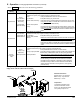
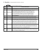
button to access the following parameters:
Factory
Setting
Range / Choices Parameter and Description
180°F
(82.2°C)
60°F to 190°F
(16°C to 87.8°C)
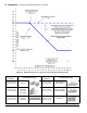
Central Heat Setpoint
Target temperature for the central heat priority. Value also used by the outdoor air reset function.
170°F
(76.7°C)
80°F to 190°F
(26.7°C to 87.8°C)
Central Heat Thermostat “Sleep” or “Away” Setback Setpoint
Thermostat setback setpoint is used when the EnviraCOM thermostat is in “leave” or
“sleep” modes and sensed at E-COM terminals D, R, and C. When setback is “on”
the thermostat setback setpoint shifts the reset curve to save energy while home is in
a reduced room temperature mode. The reset curve is shifted by the difference be-
tween the High Boiler Water Temperature and the Thermostat Setback Setpoint.
Honeywell VisionPro IAQ part number TH9421C1004 is a “setback” EnviraCOM en-
abled thermostat. When connected, it allows boiler water setback cost savings.
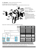
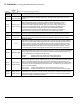
7°F
(3.9°C)
2°F to 10°F
(1.1°C to 5.6°C)
Central Heat Diff Above
The boiler stops when the water temperature rises ‘Diff Above’ degrees above the setpoint.
5°F
(2.8°C)
2°F to 25°F
(1.1°C to 14°C)
Central Heat Diff Below
The boiler starts when the water temperature drops ‘Diff Below’ degrees below the setpoint.
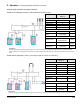
3 1 to 5
Response Speed
This parameter adjusts the Central Heat temperature controller Proportion Integral Derivative
(PID) values. Higher values cause a larger ring rate change for each degree of temperature
change. If set too high ring rate “overshoots” required value, increases to high re causing
the temperature to exceed the “Diff Above” setpoint and cycle the boiler unnecessarily. Lower
values cause a smaller ring rate change for each degree of temperature change. If set too
low, the ring rate response will be sluggish and temperature will wander away from setpoint.
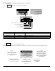
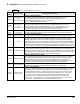
120
seconds
0 to 300 seconds
Low Fire Hold Time
“Low Fire Hold Time” is the number of seconds the control will wait at low re modulation rate
before being released to modulate. After ignition and ame stabilization periods the ring rate is
held at low re for “Low Fire Hold Time”. This delay allows heat to travel out to the system and
provide system feedback prior to the control modulating ring rate.
Supply
Sensor
Supply Sensor,
Header Sensor
Modulation Sensor
Heat Demand may respond to the boiler’s Supply Temperature or Header Temperature sensors.
When Header Sensor is selected the boiler is red in response to the sensor wired to Header
Sensor Low Voltage Terminal Block Terminals.
X. Operation F. Changing Adjustable Parameters (continued)