
Install Instructions


12 103448-08- 9/16
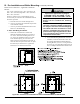
Figure 2B: Clearances To Combustible and Non-combustible Material, Wall Mounted
III. Pre-Installation and Boiler Mounting G. General (continued)
Boiler Service Clearances – Applicable to all Boiler
Models:
Top = 24 in. (610 mm), Front = 24 in. (610 mm), Left
Side = 24 in. (610 mm), Right Side = 24 in. (610 mm),
Rear = 24 in. (610 mm)
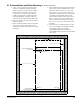
The above clearances are recommended for service
access but may be reduced to the Combustible Material
Clearances provided:
a. The boiler front is accessible through a door.
b. Access is provided to the condensate trap located
on the left side of boiler.
c. Access is provided to thermal link located at the
boiler rear (ALP285B only).
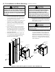
6. Boiler Wall Hung Installation:
a. If the boiler is installed on a framed wall,
minimum acceptable framing is 2 x 4 studs on
16” centers. The boiler mounting holes are on
16” centers for installation between two studs
at the standard spacing. In cases where the
boiler cannot be centered between the studs, or
where the studs are spaced closer than 16” apart,
the boiler may be anchored to ¾” plywood or
horizontal 2 x 4’s anchored to the studs.
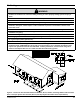
CAUTION
Alpine boiler approximate dry weights:
ALP080BW – 98 lbs; ALP105BW – 112 lbs;
ALP150BW – 136 lbs: ALP210BW – 150 lbs
Two people are required to safely lift these
boilers onto the installed wall mounting
bracket.
Make sure that wall mounting bracket is an-
chored to a structure capable of supporting
the weight of the boiler and attached piping
when lled with water. Jurisdictions in areas
subject to earthquakes may have special re-
quirements for supporting these boilers. Such
local requirements take precedence over the
requirements shown below.
b. Locate Wall Mounting Bracket Kit carton (P/N
102988-01) enclosed inside boiler carton. The
kit contains Wall Mounting Bracket, Bottom
Securing Bracket, (4) 5/16” x 2” long hex head
lag screws, (4) 5/16” at plated washers and (2)
#8 x ½” Phillips round head sheet metal screws.