
Install Instructions


103448-08 - 9/16 127
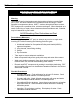
CAUTION / ATTENTION
Electrical Shock Hazard. Label all wires prior to
disconnection when servicing controls. Wiring
errors can cause improper and dangerous
operation. Verify proper operation after
servicing.
Au moment de l´entretien des commandes,
étiquetez tous les ls avant de les débrancher.
Les erreurs de câblage peuvent nuire au bon
fonctionnement et être dangereuses.
S´assurer que l´appareil fonctionne
adéquatement une fois l´entretien terminé.
exchanger using a non-abrasive, non-metal bristle
brush. Any cleaning of the combustion chamber
with acid or alkali products is prohibited. Do not
use any cleaning agents or solvents. If insulation
disc has signs of damage, it must be replaced.
8. Inspect the condensate trap to verify it is
open and free from debris. Inspect condensate line
integrity between boiler and condensate neutralizer
(if used), condensate neutralizer and the drain.
Clean/repair if needed.
If the condensate neutralizer is used, check pH
before and after the neutralizer to determine
neutralizing effectiveness. Replace limestone chips
and clean out the neutralizer if needed.
9. Inspect the ue temperature sensor cap to
verify that it is free from leakage and deterioration.
Replace if needed.
10. Inspect vent connections and vent connector
to heat exchanger seals to verify that they are free
from leakage and deterioration. Repair as needed.
Follow all instructions in Section IV “Venting” when
reassembling vent system.
11. Check for vent and air intake terminal for
obstructions and clean as necessary. Check rodent
screens in vent and air intake terminations to verify
they are clean and free of debris.
WARNING
Failure to properly secure the burner/blower/gas
valve assembly to the heat exchanger could lead
to property damage, personal injury or loss of
life.
12. Reinstall the burner/blower/gas valve
assembly
and secure with M6X1 hex ange nuts.
Tighten the hex nuts in star pattern with wrench to
5Nm (44 lbf. In) torque.
13. Reconnect any wiring which has been
disconnected.
14. Verify that the system pH is between 7.5 and 9.5.
15. Inspect the heating system and correct any other
deciencies prior to restarting the boiler.
16. Inspect low water cutoff (if used).
a.
Hydrolevel 1100H4 (100592-01). Refer to
instructions provided with kit.
i. Annual. Check operation by pressing TEST
button. See System Start-up.
ii. Every 5 years. Clean all surfaces in contact
with water.
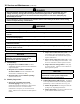
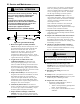
Figure 46: Igniter Electrode Gap
3. Remove the igniter assembly and ame
sensor and inspect them for oxide deposits. Clean
the oxide deposits from the igniter electrodes and
ame sensor rod with steel wool. Do not use
sandpaper for the cleaning. Inspect the ceramic
insulators for cracks and replace the igniter
assembly and/or ame sensor if necessary. Check
the igniter electrode spacing gap. Refer to Figure 46
“Igniter Electrode Gap” for details.
4. To gain access to boiler burner and
combustion chamber, rst disconnect and
remove gas inlet piping from gas valve. Then,
remove six M6X1 hex ange nuts and take out the
burner/blower/gas valve assembly from the boiler.
To prevent stud breakage, apply a generous amount
of good quality penetrating oil to nuts and let it soak
in prior to attempting nut removal.
5. Inspect the assembly for lint and dust presence.
If signicant lint and dust accumulations are found,
disassemble the blower/gas valve assembly to
expose the swirl plate and blower inlet. For parts
identication, refer to Section XIII “Repair Parts”.
Vacuum these parts as required, being careful not to
damage the vanes on the swirl plate.
6. Vacuum any dust or lint from the burner if
present. If the burner shows any visual deterioration
or corrosion signs, replace it immediately. Inspect
the burner gasket and replace if necessary.
7. Inspect the heat exchanger combustion
chamber, clean and vacuum any debris found on
the surfaces. If required, brush the coils of the heat
XI. Service and Maintenance (continued)