
Install Instructions


103448-08 - 9/16 13
III. Pre-Installation and Boiler Mounting G. General (continued)
c. 5/16 in. x 2 in. lag screws and 5/16 in. plated
washers are intended for mounting the boiler
directly onto studs covered with ½ in. drywall.
When the boiler is attached to other types of
construction, such as masonry, use fasteners
capable of supporting the weight of the boiler
and attached piping in accordance with good
construction practice and applicable local codes.
d. Make sure that the surface to which the boiler is
mounted is plumb.
e. Before mounting the boiler, make sure that wall
selected does not have any framing or other
construction that will interfere with the vent pipe
penetration.
TOP EDGE OF BOILER
'HOLE C'
'HOLE A'
'HOLE D'
LEFT SIDE OF BOILER
1.0" MIN. CLEARANCE TO COMBUSTIBLE
10.0" MIN. CLEARANCE TO COMBUSTIBLES
16
25
3
4
WALL MOUNTING BRACKET
CENTER LINE
BOTTOM SECURING
BRACKET CENTER LINE
2.0" MIN. CLEARANCE TO COMBUSTIBLE
'HOLE B'
3
16
" DIA. PILOT HOLES
FOR
5
16
" LAG SCREWS
(4 PLACES)
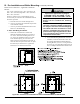
Figure 2C: Wall Mounting Hole Location / Layout
f. Once a suitable location has been selected for the
boiler, and any needed modications have been
made to the wall, use Figure 2C to locate and
layout holes “A” and “B”. These holes must be
positioned on mounting stud centers if the boiler
is installed on a framed wall. Make sure that
the horizontal centerline of these holes is level.
Holes “C” and “D” may also be drilled at this
time, or after the boiler is hung on the wall. If
the 5/16 x 2 in. lag screws are used, drill 3/16 in.
pilot holes.
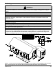
g. An alternate way to locate/mark holes “A” and
“B” is to use template P/N 102986-01 enclosed
into Vent Part Carton [P/N 102981-01
(ALP080BW/105BW) or P/N 102981-02
(ALP150BW/210W)], which can be found inside
boiler carton.