
Install Instructions


130 103448-08- 9/16
XI. Service and Maintenance (continued)
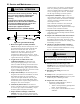
c. Disconnect pressure switch hose from condensate
trap.
d. Disconnect outside condensate compression tting
from condensate trap.
e. Using pliers, release spring clip securing the
overow switch to condensate trap body and remove
the switch. Note that the switch has factory applied
silicon adhesive seal, which may have to be carefully
cut all around to facilitate the switch removal.
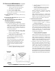
f. Using pliers, release spring clip securing condensate
trap body to the heat exchanger bottom drain
connection.
g. First, pull the trap downwards to release from the
heat exchanger. Second, pull the trap end from left
side jacket panel sealing grommet and remove the
trap from boiler.
h. To reinstall the trap, reverse above steps.
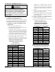
i. If the original condensate overow switch is to
be re-used, follow the appropriate switch removal
steps from Condensate Overow Switch Removal
and Replacement procedure above.
j. Insure that fresh silicon sealant is applied to the
overow switch threads and the switch is properly
oriented relative to the trap body - the arrow molded
into the switch hex side end must face down for
proper switch operation. See Figure 47 “Condensate
Overow Switch Orientation” for details.
k. Insure that pressure switch hose is reconnected to
the trap.
l. Restore power supply to boiler. Fill up the trap
(see Section V “Condensate Disposal”) and
verify the switch operation.