
Install Instructions

103448-08 - 9/16 133
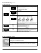
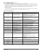
E. Active Fault Screen Faults
Indication Condition Possible Cause
Limit String Status
Limit String
Fault
The Limit String Status screen shows the faulty safety limit. A contact icon, either
“open” or “closed”, graphically represents each safety limit. The “closed” contact icon
is steady; the “open” contact icon is blinking. For example, the screen shown to the
left illustrates a “closed” Air Pressure Switch contact and an “open’ Auto Reset High
Limit contact. The Auto Reset High Limit is causing the boiler to stop ring.
NOTE: Since the limit string items are wired in series, all limits downstream of the
“open” limit will also appear on the screen as “open” (blinking) icons regardless of
whether or not they are actually open.
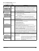
Sensor Status
Sensor Fault
The Sensor Status screen shows the status of all sensors. Possible states include:
None: Feature requiring this sensor has not been selected.
Normal: Sensor is working normally.
Shorted: Sensor is shorted or is defective.
Open: There is a break in the wiring between the Control and the sensor or the
sensor is defective
Out of Range: Sensor is defective or is being subjected to electrical noise.
Unreliable: Sensor is defective or is being subjected to electrical noise.
When a sensor fails “opened” or “shorted” the value is changed to reverse video
(background black and value white) “024” or “768” respectively to indicate that there
is a fault with the sensor.
Rate Limit
Rate Limit
The following messages appear when the ring rate is limited or reduced to help
avoid a lockout or save energy.
Refer to Hard Lockout section for corrective actions
- High Stack Temperature Limit
- High Supply Temperature Limit
- High Differential Temperature Limit
The following messages appear as part of normal start and stop sequences:
- Minimum Modulation (normal start/stop sequence)
- Low Fire Hold Rate: Low re hold rate is a normal start-up rate hold used to help
ensure system temperature feedback prior to release to modulation. Low Fire
Hold Time may be adjusted. Refer to the “Changing Adjustable Parameters”,
Paragraph F, for additional information.
- Maximum Expected Heat Rate: Maximum Expected Heat Rate limit is a normal
start-up rate hold used to save energy. This limit helps reduce extra cycles
and save energy. Boiler is free to modulate up to the sum of the active zones and
domestic hot water expected heat rates. Each zone heat rate is adjustable and
may be modied under the modulation menu. Refer to the “Changing Adjustable
Parameters”, Paragraph F, for additional information.
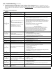
EMS Status
Energy
Management
System Fault
The Energy Management System (EMS) fault screen provides input fault status.
When an input is shown as “Not Selected” it is not required for this application or has
not yet been selected. These options are selected under the “Energy Management”
Adjust mode menu.
Modbus Input Failure If a modus input is selected and out of range or not present
a “535” value is shown reverse video (background black and
value white). To x the problem check the input source and
check that the input is properly connected.
4-20mA Input Failure Failure status for the 4-20mA input is the same as shown
under Sensor Fault.
XII. Troubleshooting (continued)