
Install Instructions


14 103448-08- 9/16
III. Pre-Installation and Boiler Mounting G. General (continued)
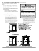
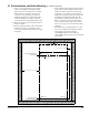
Figure 2D: Bottom Mounting Bracket Installation / Boiler Wall Mounting
BOILER
WALL BRACKET
BOTTOM
SECURING
BRACKET
5
16
" X 2" LAG
SCREW (4X)
5
16
" X 2" FLAT
WASHER (4X)
2 X 4
WALL STUD
16" C/C
BOILER HANGING
BRACKET
BOILER
#8 X
1
2
" SMS (2X)
1
2
" SHEET
ROCK
BOILER HANGING
BRACKET
BOTTOM
SECURING
BRACKET
CAUTION
When positioning the template in the desired
location on the wall insure that the minimum
clearances to combustible material at adjacent
walls and ceiling are maintained. Consult
Figures 2A through 2C in this manual. Be sure
to allow space at the boiler left side for gas and
water connections, as well as for access to the
condensate trap and boiler controls for servicing.
m. See Section IV Venting; Paragraph B, 4 “Field
Installation of CPVC Vent Pipe - Wall Mounted
Boiler Builds” for instructions on attaching the
vent system to the boiler.
WARNING
Vent pipe must be inserted rmly into vent
connector and secured by tightening the metal
strap worm screw.
n. After the boiler has been piped, wired, connected
to vent and combustion air system piping and
combustion performance testing completed per
Section IX “System Start-up”, install Access
Panel/Gasket assembly and secure with provided
four #8 x ½ in. black oxide Phillips head sheet
metal screws. See Figure 2E “Access Panel and
Gasket Installation”.
CAUTION
The outer edges of the template represent
minimum side, top and bottom clearances to
combustible material. If the template needs to be
cut to t into a selected location, it would indicate
the minimum clearances to combustible material
are not met.
h. Attach the wall hanging bracket using the 5/16
in. x 2 in. lag screws and 5/16 in. plated washers,
or other suitable anchors as appropriate (Figure
2D). Make sure the bracket is level.
i. Attach Bottom Securing Bracket to boiler air box
with two #8 x ½ in. Phillips round head sheet
metal screws. Refer to Figure 2D for details.
j. Hang the boiler on the installed wall bracket as
shown in Figure 2D.
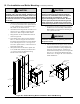
k. If not already done in Step (4) locate and drill
holes “C” and “D” using the ob-round slots in
the Bottom Securing Bracket. Secure the Bracket
to the wall using the 5/16 in. x 2 in. lag screws
and 5/16 in. plated washers, or other fasteners as
appropriate (Figure 2D).
l. Verify that the front of the boiler is plumb. If it
is not, install shims (installer provided) at holes
“C” and “D” between the Bottom Securing
Bracket and the wall to adjust.